· Products · 18 min read
Prototyping: Wemos S2 Prop Board
Designing prototype version 2 of the custom prop board
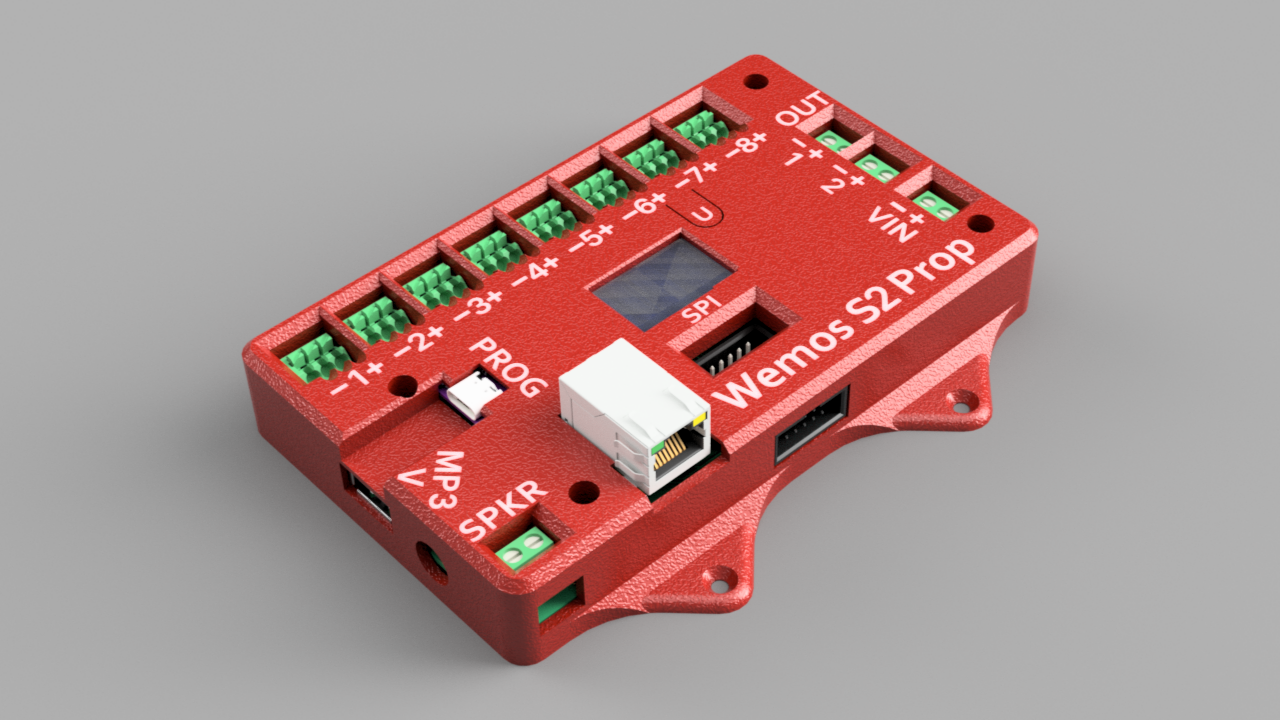
After designing and implementing the Wemos D1 board, I moved on to design another board to tackle the problems present in it. My primary design goals for this board were:
- Reduce board size
- Correct board mistakes
- Choose a single microcontroller
- Implement RFID modules
Circuit Design
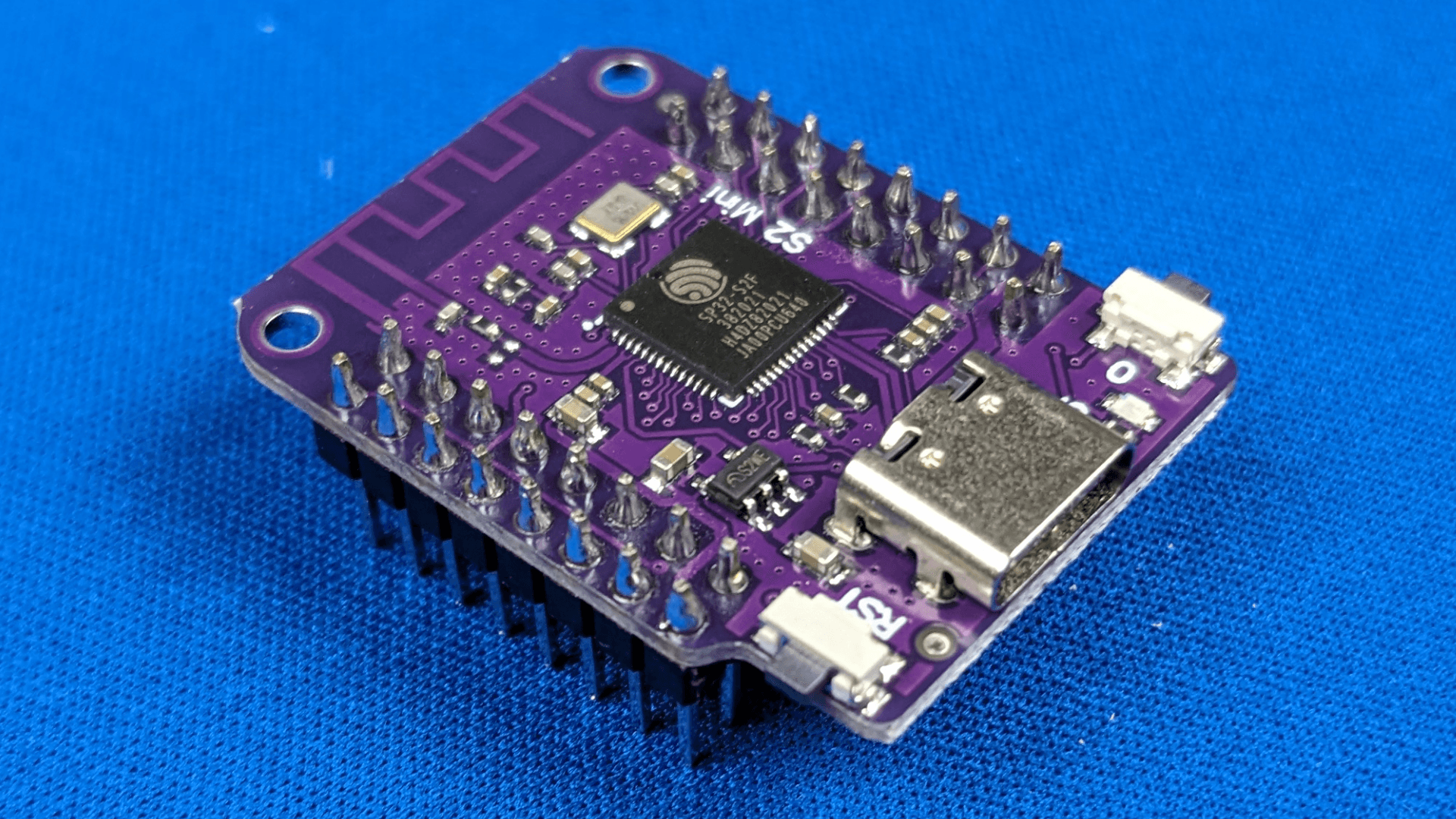
The microcontroller choice heavily influences the rest of the list, so I tackled this choice first. To have one microcontroller perform what used to be the job of two, I need it to contain a generous amount of GPIO pins. Otherwise, I would need to start adding GPIO expanders into the design, which will add cost and complexity in both programming and hardware I can tackle, but would prefer to avoid until necessary. I settled on the Wemos S2: an ESP32-S2 based board which has over 40 usable GPIO pins, 20 of which are analog capable. The form factor is nearly identical to the Wemos D1, with an additional column of pins on each side. The modules can also be found online at a fairly affordable price, which makes it easier for prototyping.
The wiring mistake with the resistor dividers was corrected. The incorrect labeling on the board was rectified as well. To condense the board down, I opted to remove most of the PCB labeling on the inputs. This allowed me to pull the spring terminal blocks closer to the inside of the board, eliminating dead space that was reserved for labeling. I decided that labeling of the inputs and other peripherals could be done on an enclosure, and the inclusion of an enclosure would also take care of the issue of stray wires and strands getting inside and causing shorts.
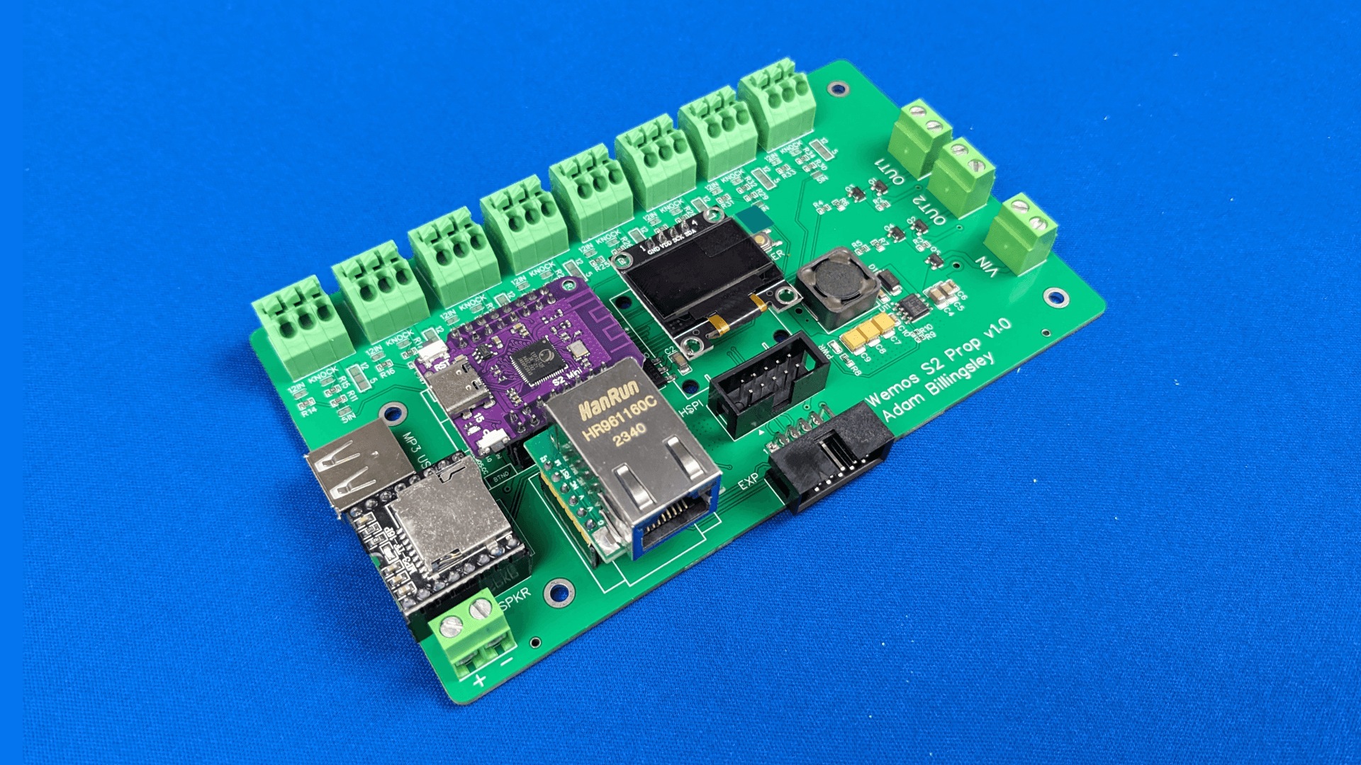
To further reduce the board size, I needed to either change the input headers or reduce the number of inputs. I’m still a fan of the spring terminal blocks, so I kept the headers. Digging into my history of props, I can ballpark the typical prop involving 4 sensors on average. Of the individual puzzles implemented on the previous board only a single puzzle required more than 8 inputs. Doubling my average use case seemed reasonable, so I opted for 8 inputs. I also reduced the number of outputs down to two, since a single prop involves 1-2 power outputs most of the time.
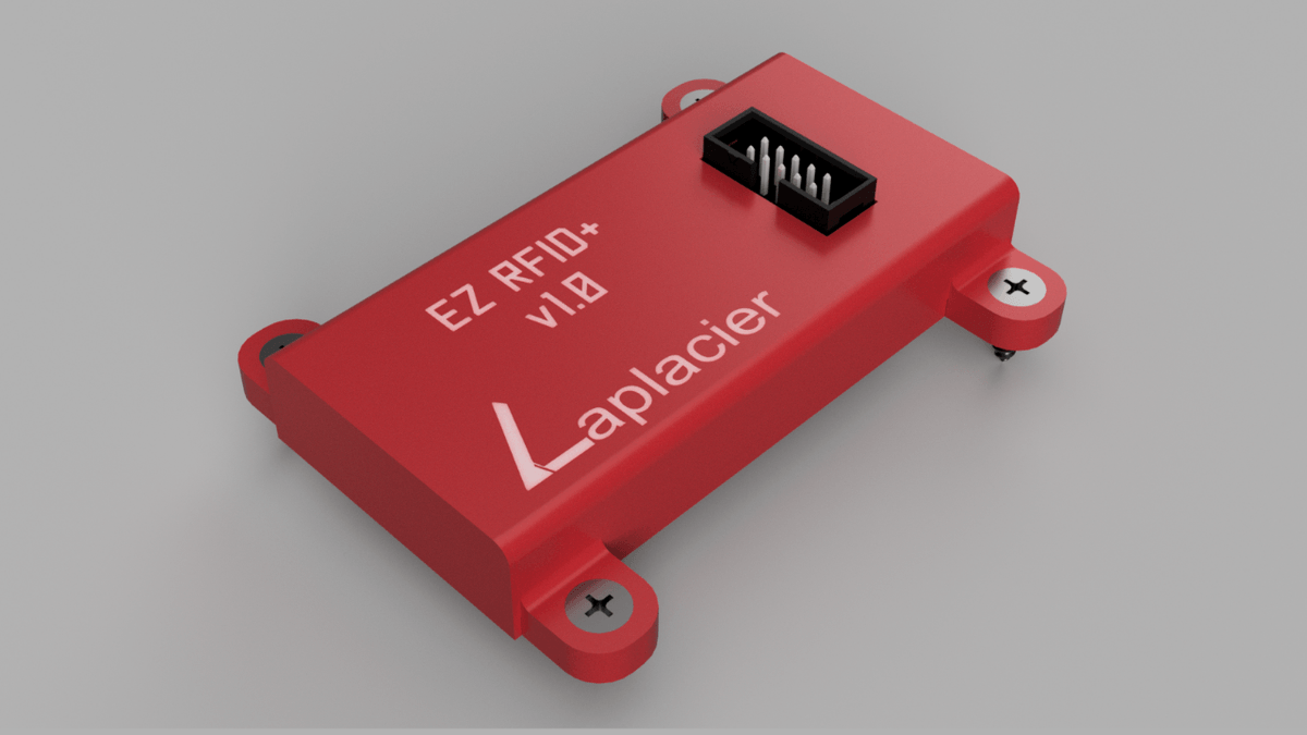
During this time I also implemented the PN5180 module, which I detail in another post, as a standalone device with a simple plug-n-play interface. To interface these with my board I would need to add an IDC header with the necessary SPI connections to the microcontroller. These headers also take a generous amount of board space and quickly eat away the available GPIO pins to use on the board.
RFID props are typically an all-or-nothing package. Props that implement multiple RFIDs are going to exclusively utilize RFIDs, and those that don’t will need one RFID at most. Knowing this, either additional hardware to reduce the amount of pins to the board would be required, or another board would need to accommodate multiple RFIDs.
Reducing pin count would require the RFID modules to have standalone microcontrollers to process the data and push out the data over the preferred low pin count protocol of choice. This is the design that the consumer boards choose. The issue I have with this approach is the cost. You can boast your ability to push data over long distances with this design and keep it compatible with the same board, but then you run into the problem of selling a simple 4 RFID prop with a hardware cost of several hundred dollars on top of the development cost of introducing a new board to develop.
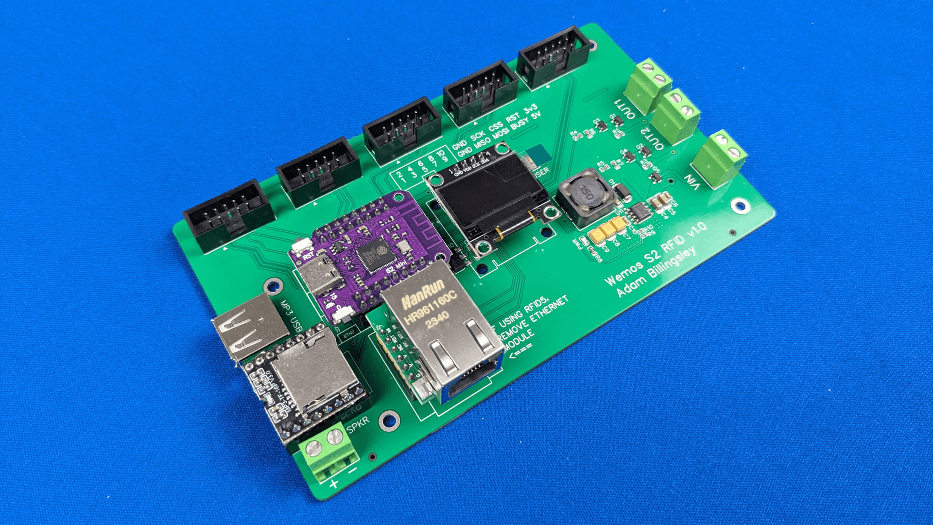
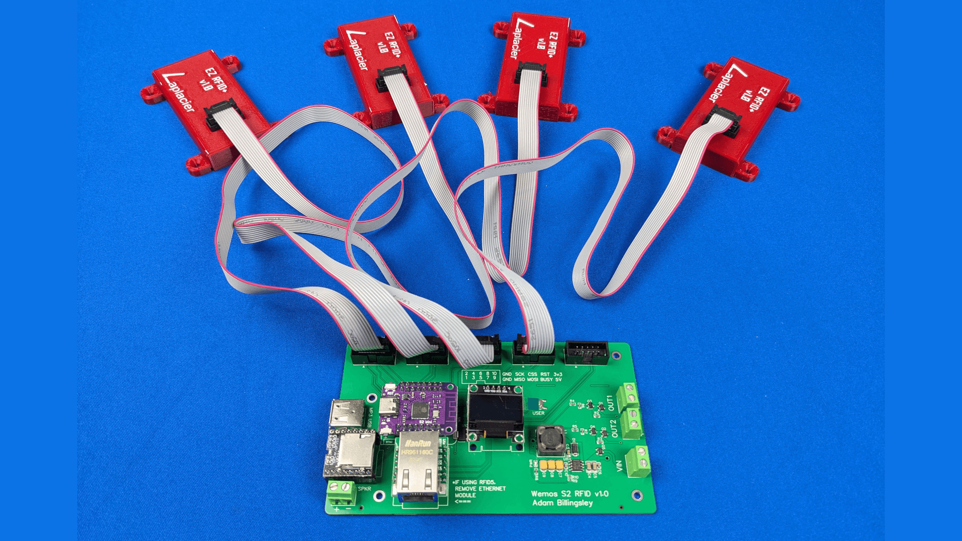
It makes more sense to keep the costs reasonable and have a board dedicated to using multiple RFIDs. With the Wemos S2 I have enough GPIO to implement 4 RFIDs on an SPI bus, and a 5th if ethernet is disabled. On the regular board, I had free space for two RFIDs. I implemented one RFID on the regular board and exposed the rest of the spare pins on an IDC header pointed at the edge of the board for future purposes. If I needed to develop additional IO for props that required more, I could utilize that extra header to plug in the hardware to do so. I took the design of the regular board, cut off the terminal block headers, and replaced them with IDC headers to plug in the RFID modules for the RFID board design.
Programming
With the previous design, two microcontrollers were involved, which made asynchronous tasks much easier to perform. I now have a microcontroller with the responsibility to perform all of these tasks and a single core to do them on. Luckily, FreeRTOS is heavily supported on Espressif chips, which includes the Wemos S2, so I adopted this framework to manage each task. I also decided to shift programming work towards ESP-IDF instead of continuing with the Arduino ecosystem. Arduino is powerful, and I still use it to quickly test new sensors and peripherals, but the level of abstraction between the Arduino core and what is happening on the microcontroller is too high for Espressif chips.
Compared to Arduino, in which you have a setup loop and a mega loop in which you define your logic, in FreeRTOS you create tasks with a priority, allocate stack (memory/space) to the tasks, and each task takes turns performing their logic based on their priority, creating an asynchronous flow. It’s analogous in nature to a task manager in a modern operating system, where multiple processes can be seen running on a computer as well as the amount of resources they are utilizing.
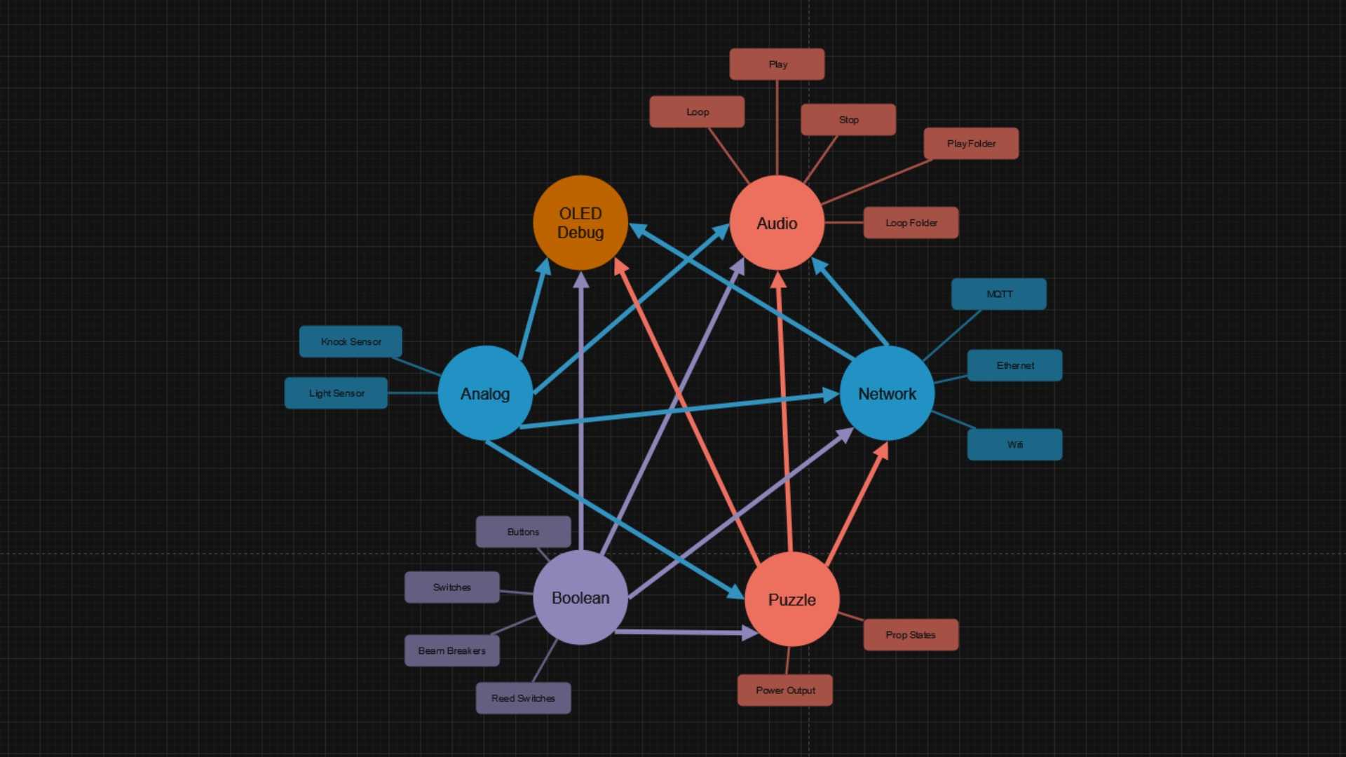
In order to transition to FreeRTOS, sensors need to be reenvisioned as tasks. Duties that the microcontroller needs to perform must be categorized, grouped, and assigned to these tasks. Looking at the board from a physical perspective, we have network, audio, inputs, power outputs, and an OLED display. A network can change based on which peripheral serves as the network, so I divided this into a wifi and ethernet task. Audio could encompass different interfaces as well, but since this board has a dedicated DFPlayer it will serve as the audio task. The power outputs only serve to turn a single amount of power on and off at infrequent intervals, so this role was minor enough not to not dedicate to a task. The OLED display serves to display information about the board as a whole and requires a fair bit of processing to refresh the display, so a dedicated task for this is reasonable.
The inputs need to be split up, due to the vast ecosystem of sensors it encompasses. A boolean task can encompass any sensor that operates on a single true/false signal, such as buttons, limit switches, and beam breakers. A generic analog task can handle light sensors and knock sensors. Encoder task can manage encoders, RFID task can handle RFIDs, and LED task can handle LED strips.
The puzzle logic can be implemented as a dedicated puzzle task. For each state it can wait for the conditions to be met by other tasks without having to constantly poll any sensors itself. It simply waits for new data and checks if it meets the criteria to change states before waiting again.
For each task, a queue can be implemented to receive data from other tasks, facilitating the ability to pass data between each other. If a button is pressed, the boolean task can notify the ethernet task and the puzzle, and a command over the network can be received by the ethernet tasks and sent to the appropriate task.
Preprocessor definitions were added throughout the code to facilitate setting up the inputs and outputs. By defining the use case of the board through these definitions, only the necessary tasks would be created for the prop. Certain checks were also implemented to prevent errors, such as preventing sensors from being defined on the same input.
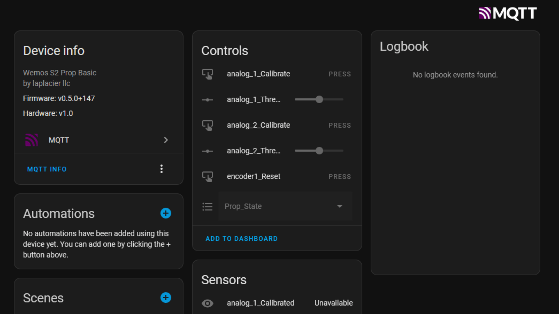
Another weak point I decided to tackle with this design was the user interface for Homeassistant. I’ve always manually created MQTT sensors on Homeassistant to detect all of the topics for each prop which takes a considerable amount of time. Fortunately, there is a way to make Homeassistant automatically discover your device and set up the correct sensors through a special discovery topic. By creating a method on the prop to send these discovery messages based on how it is configured, I no longer had to manually add the device to the interface - I just needed to make them look pretty which is quick with Homeassistant!
Modeling
Although the board did get significantly smaller, the required model is still going to be a larger model than what I’m accustomed to constructing at the time of writing. I want to have quick access to the solder pads on each input while also keeping them protected, so the top needs to be removable even when mounted inside the prop. This means the method to secure the top needs to come from the top. I thought that a simple snap fit would not suffice for something of this size, so I designed the board to be screwed in through the M3 holes on the board. The board would rest inside the bottom half of the case with an air gap underneath to facilitate airflow, and M3 screws enter from the top, through the M3 holes in the PCB, and into some heat inserts welded into the bottom case. Holes and gaps are placed where necessary to access all the peripherals, and labeling is included on the top.
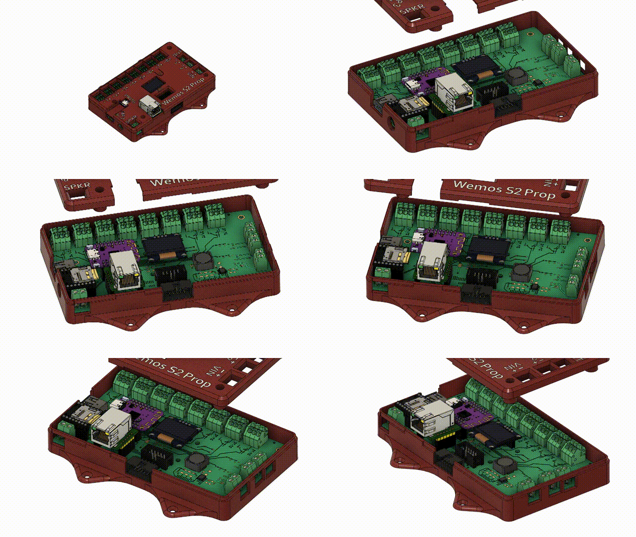
The design went through several iterations while I learned the limitations of text size for a 0.4mm extruder. I also had to hollow out the top in various iterations to ensure peripherals didn’t bump the top of the case due to conflicts with the dimensions of the models and the board. Once finished, the end result looked fairly decent and had acceptable labeling.
Performance on Site
Using this set of boards I have replaced hardware in a prop involving several types of peripherals for one room, an RFID prop and boolean prop in a second room, and an entire system replacement of a third room. The redesign sped up several elements of the install, but the state of the code introduced some new issues to tackle that slowed down the process. Overall, time on site was still reduced and shows that there is great potential in this method as long as the issues are resolved.
Improvements
With the wiring mistakes from the previous board design resolved, what would have been 2-3 hours of delicate labor per board was now eliminated. Every input configuration was presoldered beforehand and brought on site ready for their respective prop.
Making a change to the programming now required the maintenance of one program instead of two.
The wiring was even easier to manage than before, and I had now implemented a method to create board labels specific to the prop itself. This made explaining the setup to the customer much simpler, since the black wire from “the top left encoder” now plugged into an input labeled “BLK ENCODER TL” instead of “3”.
The smaller form factor of the boards made them easier to mount inside props. The enclosure facilitating wood screws also simplified the process.
The largest labor saver by far was the standalone RFID board for the RFID props. There is a minor amount of setup at home assembling them compared to the hours of creating 9 stranded cables by hand. The on site install went from a delicate manipulation of several wires that required lots of testing to plugging in cables, changing 1-4 strings in the code, flashing the board and closing up. Over half a day of labor is saved off each RFID prop compared to my previous “from scratch” method.
With the autodiscovery feature of Homeassistant, I was also forced to standardize the method in which all props broadcast their states and accept commands so that the prop could create them systematically. This, on top of the implementation of autodiscovery, reduced the post install programming for a room from a day to a couple hours. No reboot to update any manual changes on Homeassistant was required in this implementation either, which meant no idling around waiting for a gap between games to reboot.
Disadvantages
The wifi cabilities of the board are nonexistent. The PCB antenna trace has a weaker signal strength than the previous Wemos D1 with it’s integrated wifi module, and design mistakes on the board further diminish its strength to the point where it is unable to function. The microcontroller is in the middle of the board, which completely surrounds the antenna with potential hardware interferences, and there is a 3.3V regulator and ground plane directly underneath the antenna. Network connectivity with this version of the board is limited to ethernet.
I had some props that would require rapid triggerring of the audio by design. The DFPlayer has several variants, and the 3 different models I had at my disposal all locked up when sending commands to them too quickly, requiring a power cycle to resolve. After a long search online, It’s come to my realization that the “good’ variants are nowhere left to be found, and updated versions are much more expensive than the original. I’m going to conclude that the DFPlayer is fine for the most part, but it isn’t reliable enough to merit using as a staple audio device in my props moving forward. Some Espressif chips support I2S audio, therefore an integrated solution may be an option.
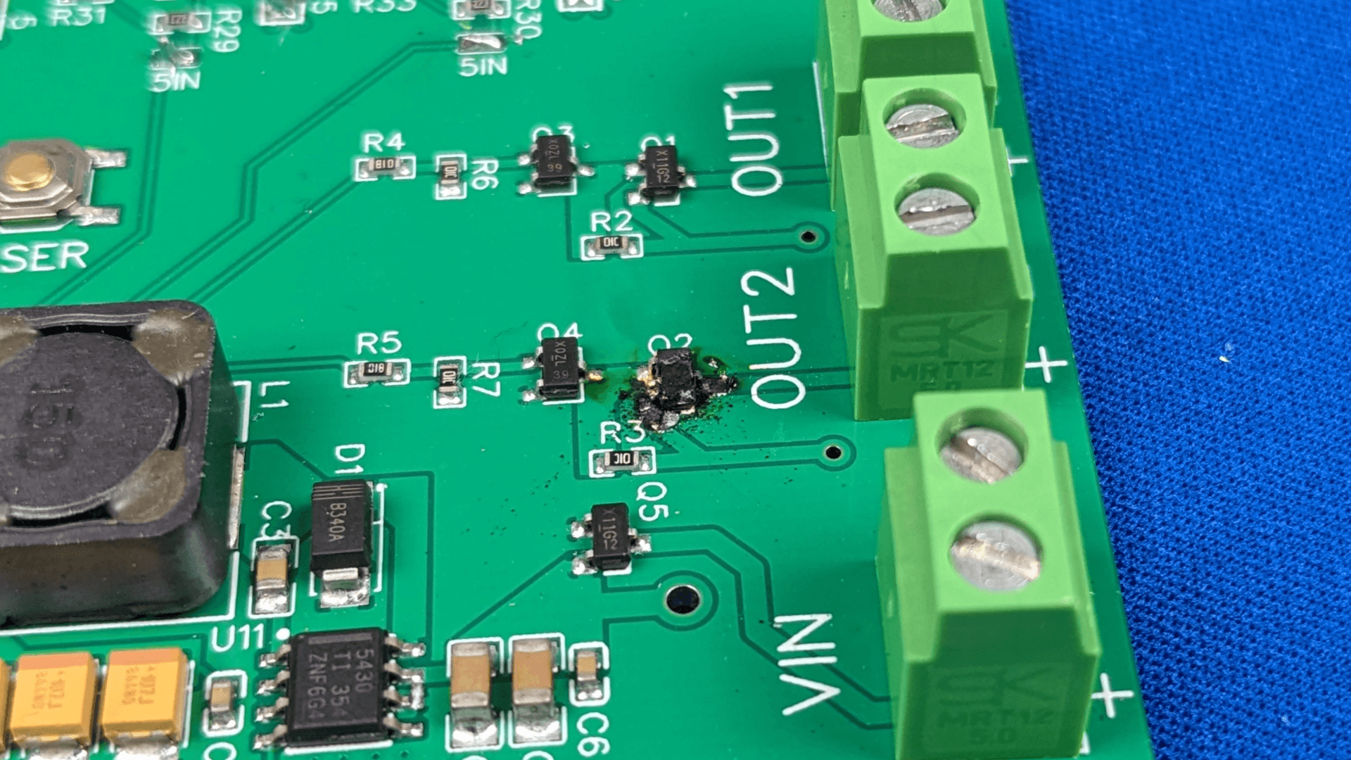
One of the props had a preinstalled 12V solenoid lock which was broken and shorted (not known at the time). Powering this lock through the board caused the p-channel mosfet on the high side of the output to destroy itself. Somehow throughout this process I didn’t take into consideration any circuit protections around the power outputs aside from protecting the GPIO pin controlling it. The next design needs current and reverse polarity protection. Reverse polarity protection currently exists on the board power input, but not the power outputs. Since the board power input and the power outputs have the same current limits, a fuse on the board power input should take care of current protection. Implementing a flyback diode to handle the kickback of any relay or solenoid discharge would be good practice too. Fortunately, the p-channel mosfet was the only component damaged by mishandling the power output, so I can create a strategy around protecting that.
For cases where no modifications had to be made, the new firmware for the props was quick to implement and worked great. For props where non-standard puzzle logic needed to be inserted, which was most of them, it was not so great. I quickly came to discover that my code was written in such a way that making a sensor trigger something I did not preprogram it to perform required modifying code in several different files. Said files are all considerably large and difficult to parse through, even as the author of said files, thanks to removing the abstraction that Arduino provided. The removal of abstration was necessary in order to have full control over the process, but it was clear the current method was not correct and needed to go back to the drawing board.
What’s Next
The problems outlined in the installation of the previous boards mandate a new board design. Wifi needs to function, outputs need to be protected, audio needs to be more reliable, and the code structure needs an overhaul.
Efficient Prop Programming
Speeding up this process is going to require me to step back and determine how to structure the code and flow to ensure it is easier to maintain and make additions. The key issue is how the tasks communicate with each other. If I make a change in a task in the current code, I need to ensure that change is compatible as it propogates information to the tasks it sends information to. The tasks on the receiving end, as a result, need to be modified to identify the new information and accept the change as well.
A code restructure is required, and the following goals need to be met:
- All puzzle logic needs to live in the puzzle, not in the various tasks it acquires information from.
- Standardize the communication between the task of a peripheral to any destination outside the task.
- Minimize the code dependencies of tasks upon other tasks.
- Standardize error messages and error management.
No Flashing, Just a Config
If prop logic is limited to one source, it isn’t unreasonable to take it an additional step and store prop instructions in a configuration file. The file can define what sensors are installed and how the board needs to behave on each prop state. If a prop is ever introduced that the configuration isn’t equipped to handle, then the firmware could be updated to handle those cases as they arise. I can program as much prop logic as I can account for and play whack-a-mole with the new logic, implementing them as firmware updates.
I’ll need a method to deliver the configuration to the board. The three options readily available with the current microcontroller and programming are a self hosted webpage, SD card, or flash drive. SD card and flash drive would require additional hardware, but the webpage would not.
Audio
The DFPlayer, which has served me well for several years, is hitting limits in functionality and needs to be retired. A new audio method is required.
Most Espressif chips support the I2S protocol, which can output audio and is probably going to be the next iteration of audio for the board. With this method, the microcontroller will be responsible for decoding and outputting the audio rather than sending a command to an external device to perform those tasks. Code will need to be created to decode various audio formats into I2S waveforms for physical playback, and a circuit will need to be created to amplify the signal for direct output.
Lighting and Displays
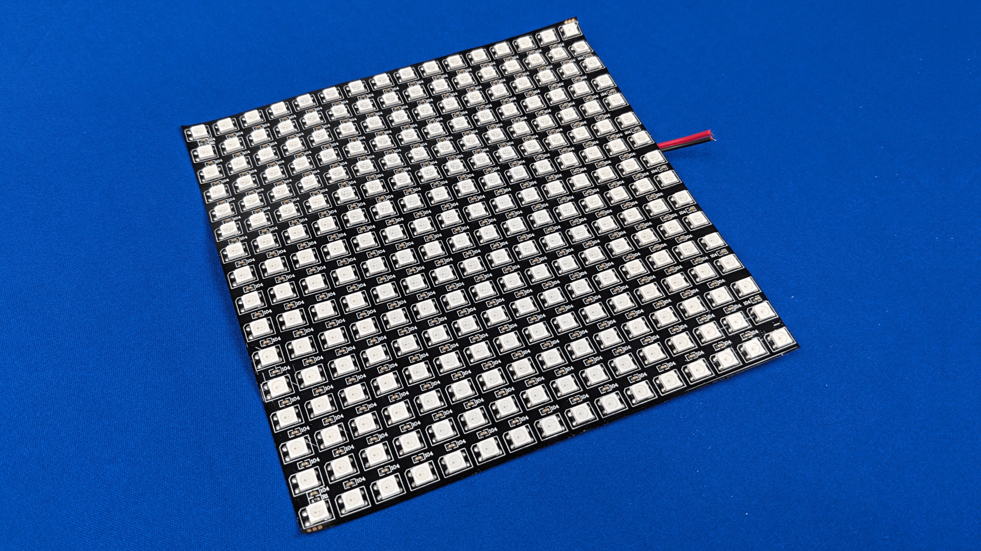
My board is not well equipped to perform any major LED animations or implementations. The amount of CPU involved in managing larger pixel densities and counts requires a microcontroller to be dedicated to that task. I believe it is reasonable to require a dedicated board for graphics.
For large RGB LED strips and matrices, WLED is, by far, the most powerful tool for animation and is licensed in a way that allows me to use it in my installations. Any system that I implement in the future for LED strips is going to be running off of WLED, and I need to work on implementing it in my projects. This also requires me to tackle the challenge of providing enough power to these light arrays and injecting power in regular intervals to avoid voltage drop.
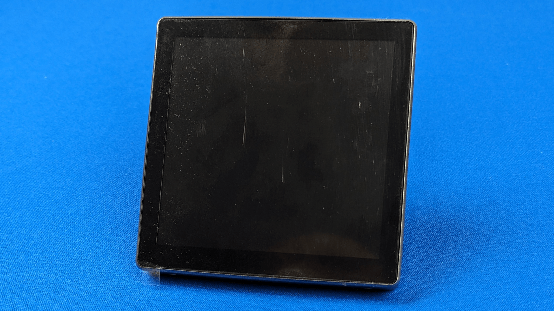
TFT displays with high pixel density and touch capability are a great prop feature I’ve yet to implement but need to add to the arsenal. Luckily there are some affordable options that come with an embedded Espressif chip to test and program with. Some even look like good drop-in devices.
Running a full blown TV is best left to embedded Linux devices that have HDMI capability. In the past 5 years the only device family I see used for this purpose is the Raspberry Pi. It’s small, cheap, and has a large community ecosystem to grab ideas from on how to implement them into installations. I also used Raspberry Pis to run TV displays, but the recent years have decimated the available supply of devices. The company has rattled off a few reasons for shortages and assures that the shortage is temporary. I’ve been on the hunt for equivalent solutions and so far not yielded any results. Solutions have been created and become available due to the gap, but they too have been cleaned out.
More Sensors
There are more sensors and peripherals out there that I have used and need to be implemented as components in the code, as well as peripherals I could potentially use or may not be aware of yet. With the code overhaul, these should be much easier to introduce to the ecosystem.
Last Thoughts
We’re getting closer to a board ecosystem I can be happy with: boards that are optimized for quick and clean installation, provide the room operator with the features they need to run the room effectively and with minimal training, and don’t break the customer’s wallet. If we make it to the end and complete a non-prototype design, I believe this could even be a product that sells by itself! There’s at least one more prototype and additional designs as needed to catch additional bugs or features standing between that goal. However, this adventure started with my frustrations with the existing ecosystem of controller boards. Creating boards, seeing these problems get eradicated, and seeing the boards transform into viable products with my own efforts is already a reward in itself.