· Products · 34 min read
RFID Programming and Design
Programming and modeling an EZ RFID reader from scratch with the PN5180
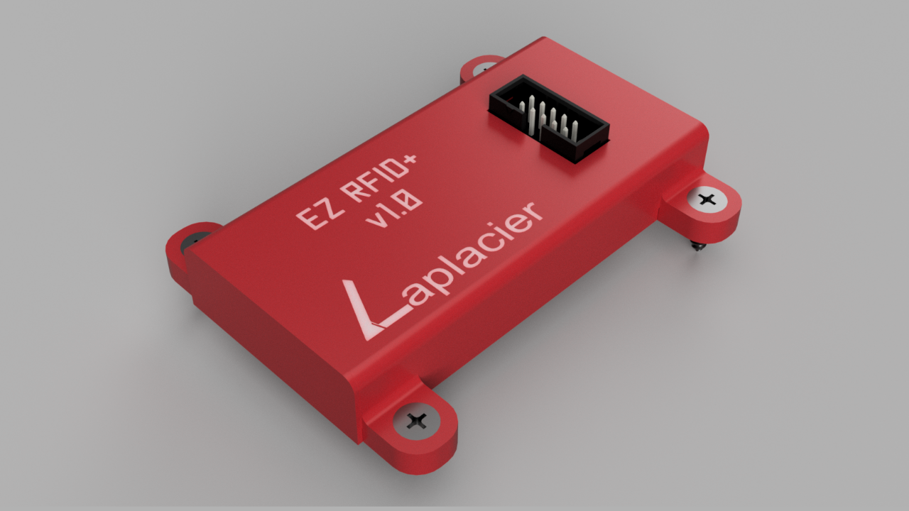
Over the years I have used a fair share of cost-efficient RFID readers to implement RFIDs into projects and escape rooms. Nothing has come close to the reliability to the price threshold of the PN5180. I have been able to sense certain tags as far as 6 inches from the surface of the reader through most common materials. Publically available libraries exist for the reader, but their implementations are either incomplete or lacking certain flexibility that would allow them to be significantly easier to implement. I want to implement those improvements, as well as reduce the amount of labor required to go from start to install.
Choosing a Framework
It’s easy to jump into the Arduino IDE environment. There is an insane level of open source community support that no other platform provides. Going from unknown to implementation of a sensor is as simple as typing “name of sensor Arduino” in the search engine and finding examples from someone who did it first, which removes all of the trial and error of figuring out how to interface with the sensor.
However, it is for this reason that I did not choose the Arduino environment. It is too easy to dive into the world of open sourced libraries for sensors, slap it into your program, and begin scratching your head when something misbehaves a few weeks later. For dedicated Arduino microcontrollers this is not much of an issue; you can simply debug the code as normal and move on. You might even find an issue stemming from the library itself and make your own contribution to the open source community as a result.
void className::init(){
  pinMode(LED_BUILTIN, INPUT); // Does my board even have an LED_BUILTIN??
  /*
   * What SPI pins did it just use by default?
   * Is this half duplex? Full duplex?
   * What bus is it attaching to?
   * Can I even change any of this behavior easily?
   */
  SPISETTINGS(FREQ, MSBFIRST, MODE0); // ?????
}
Non Arduino microcontrollers utilizing the Arduino environment are not so clear. There is an extra layer of abstraction between Arduino and the native framework of the microcontroller. You may be setting a pin as an INPUT_PULLUP in the IDE, but behind the scenes something much different is going on that you will not see in plain text to achieve that on non native frameworks. Knowing what is occurring requires digging through several layers of the microcontroller’s core files for Arduino, and matching each Arduino function with the resulting commands to the microcontroller. It’s a lot of labor.
This came to a boiling point for me when attempting to interface PN532 RFID controllers. I made a simple prop to detect a tag on a single PN532 and then play a sound clip. I interfaced this with an ESP8266 in a quick and dirty “this needs to be done right now” job using a publicly available library and Arduino IDE that is quite popular for the device. Not much needed to be changed from the included examples aside from adding a music player. When observed, it ran fine. After a few days of running it would completely lock up, preventing any tags from being read. I tried every method of pinpointing the issue at my disposal for the device, but when the inevitable “lock up” would occur, the device would, as expected, lock up and prevent any information about the event from being sent. Debug prints, error stacks, and all were unable to be retrieved due to the nature of the failure and lack of native framework components to handle the issue.
Waiting for tag...
Found tag! (UID)
Waiting for tag...
Found tag! (UID)
Waiting for tag...
...
(Proceeds to hang indefinitely, no info here)#include <customSPI.h> // What's in here?
bool PN532::waitForTag(int timeout){
// Timeout doesn't prevent hang, in spite of code saying otherwise...
if(!timeout && found) return true;
return false;
}// You've got to be kidding me...
#ifdef BOARD_A
Many();
SPI();
Functions();
#endif
#ifdef BOARD_B
Many2();
SPI2();
Functions2();
#endif
#ifdef BOARD_C
Many3();
SPI3();
Functions3();
#endif
#ifdef BOARD_ABCDEMy current ecosystem utilizes a variety of ESP32 microcontrollers. In light of the aforementioned issues that might arise, I decided to build this library in its provided framework: ESP-IDF. It also has its own implementation of FreeRTOS built in which I enjoy taking advantage by turning each portion of a prop into a “task” that runs in the background.
Programming the PN5180
Compared to writing embedded code for buttons, lights, or other basic components, code for the PN5180 is significantly more involved. Some protocols are handled automatically or are significantly simplified by the device, such as authenticating Mifare cards or tuning the RF gain to accept different protocol cards, but all of this still needs to be called via an SPI interface in the correct order. This is also accompanied with checking several different registers in between each step and ensuring they are all flagging a correct state.
All of this information is included in a whopping 150 page datasheet, entailing a different process required for each type of ISO protocol. This doesn’t include the required protocols for exchanging data between the cards of various ISO protocols, which are just as wordy and locked behind ISO specifications that you must pay to access and read. This ALSO doesn’t include the datasheets for each manufacturer’s RFID tags describing important information such as volume of storage, how they’re structured, and which sections are read/write compatible or encrypted. Suffice to say, creating a library from scratch for an RFID reader is not for the faint of heart.
Hello World
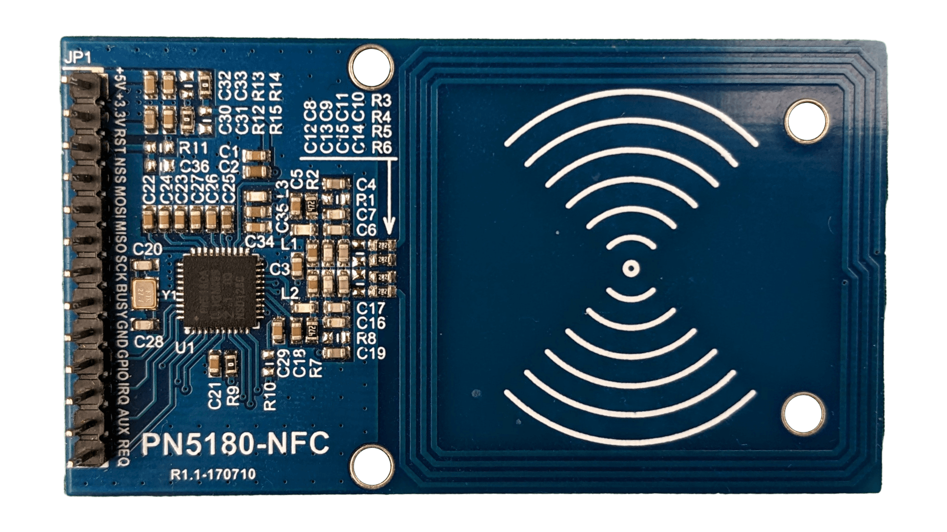
The PN5180 is a GPIO hog. It requires the standard SPI pins (MISO/MOSI/SCK/NSS), an external reset pin, and an external busy pin. On top of that it requires both 5V and 3.3V power for various peripherals on the board. 9 pins required to get this reader running at minimum. Each additional reader on the SPI bus adds an additional 3 GPIO pins for dedicated NSS, reset, and busy pins. Therefore if you wanted to run 5 of these together you would need 21 GPIO pins dedicated to this task.
The maximum speed supported by the PN5180 is 7MHz, which we can easily crank up to that level with an ESP32. It also runs in SPI Mode 0. Communication works as expected when talking to the PN5180 and manipulating the device itself, supporting the standard ESP-IDF commands for sending and receiving SPI data as long as the following sequence referenced by the datasheet is adhered to:
- Assert NSS to Low. If the NSS pin is configured with the ESP-IDF settings, this is automatic.
- Perform Data Exchange. Perform the ESP-IDF command spi_txn.
- Wait until BUSY is high.
- Deassert NSS. The datasheet states this is the 4th action in a sequence, but it doesn’t seem to matter if you deselect the reader before it flags itself as busy. Therefore ESP-IDF does this automatically and everything is fine. As a result, step 3 is redundant and can be ignored.
- Wait until BUSY is low. Simple enough. Read the busy pin with a timeout so we avoid waiting forever if there’s an issue.
The revised steps for ESP-IDF, after some testing and optimizing them for a bit, is the following:
/*
 * Before starting an SPI transaction, wait for BUSY to be low.
 * If firing out transactions in rapid succession you can outrace
 * the BUSY pin so a check is necessary.
 */
uint8_t counter = 0;
while(busyPin){
  async_delay(ms); // Do other tasks...
  counter++;
  if(counter >= TIMEOUT) return true; // Timeout when stuck
}

// Perform the SPI transaction.
spi_transaction_t txn = {
        .length = (size_t)(txLen * 8),
        .rxlength = (size_t)(rxLen * 8),
        .tx_buffer = tx,
        .rx_buffer = rx,
    };

// Wait for BUSY to go low again
counter = 0;
while(busyPin){
  async_delay(ms); // Do other tasks...
  counter++;
  if(counter >= TIMEOUT) return true; // Timeout when stuck
}

return false;
I used a digital logic analyzer to check and ensure all these signals were timed properly without any additional fuzz. Sure enough, ESP-IDF conveniently matches all of it on its own. You can see an example below:
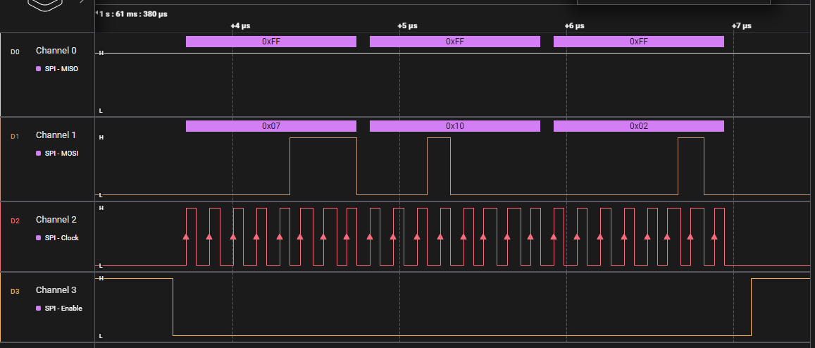
In this first exchange, the ESP32 sends a request to the PN5180 for it’s product version: the original version of the firmware flashed to the reader.
(0x07) Read EEProm, (0x10) Read the product version stored in EEProm, (0x02) I want to read two bytes of data at this EEProm address
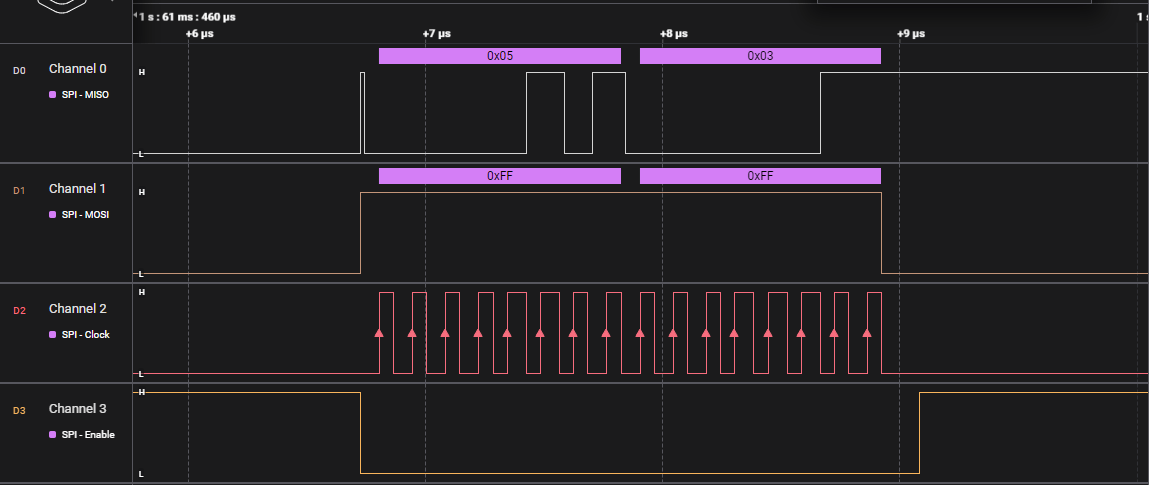
The second exchange is the response from the PN5180. If it returns 0x00 or 0xFF we know something is wrong. This exchange is correct.
(0x05) Minor version number, (0x03) Major version number
The PN5180 gives us a product version of v3.5, a common version of these devices and our first correct response from the device. Hello World!
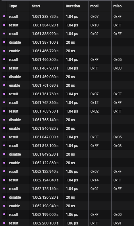
From here I’m able to push forward with communicating with all of the registers and addresses outlined in the datasheet. They’ll be accessed extensively, so functions get created for those.
Talking to RFID Cards/Tags
The PN5180 is capable of communicating with the following types of RFID cards:
- ISO 14443-A/B/C
- NFC Type 1/2/3/4A/4B
- ISO 15693
- ISO 18000-3 Mode 3 (18000-3M3)
It can also pretend to be an ISO 14443A card, for other readers to pick up.
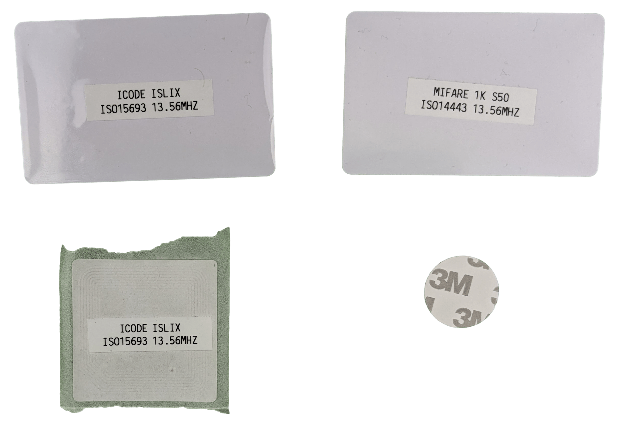
Ideally I communicate with all of the tags, which I plan to do eventually, but first I’ll stick to the types that I have in my possession: ISO14443-A and ISO15693 cards. These are widely available and are very cost effective cards. A pack of 100 of these types go between $15-$20 depending on where you look. The larger cards detect from further away than the smaller cards, and the ISO15693 cards detect from further away compared to the ISO14443-A cards. The difference isn’t too severe though, so unless we’re trying to hit the limit of the reader’s detection range we should be fine using all of them. The reader is the main performance factor.
The PN5180 specifies several configurations with different data rates that it can support with these cards. The higher the data rate, the faster the exchange. However, there is a tradeoff of not supporting cards which might be in spec but are not capable of the high data rates. To be on the safe side, I’ll hard encode the most compatible data rate. In my applications, the speed of transfer of a few blocks of data will be negligible no matter the data rate.
Both protocols I plan to implement for this first draft have their own ways of communicating that require their own methods. It’s worth breaking these out into their own sections.
ISO 14443A (Mifare)
According to the ISO 14443-3 specification, the following actions are required to communicate with a card:
- Perform an anticollision sequence until the card is found
- If necessary, perform authentication with the card (we have to do this)
- Perform reads/writes with card
- Halt or deselect card when finished
The anticollision protocol is a mess to navigate through. Commands must be sent to the PN5180 to perform each step in order, reading the registers after a small delay to check what happened. Some commands will reply with something indicating a failure in its own unique way, some don’t reply at all when failing, and in the worst case some commands give no response regardless of a success or failure. In the worst case, I have to execute the next command and check if it succeeds.
Note that this is a simplification of the process. The anticollision steps for the PN5180 are:
setCrypto(false); // Disable encryption
setCRC(false); // Disable CRC checks

pn5180CardCommand(REQA); // Send REQA command

uint32_t regData = checkRegister(RX_STATUS); // Check for response
if(!(regData >> RX_LENGTH)) return true; // Proceed if response (ignore data)

uint8_t cmd[] = { CASCADE_LV1, NVB_20 }; // Prepare 1st anticollision
pn5180CardCommand(cmd); // Send command

uint32_t regData = checkRegister(RX_STATUS); // Check for response
if(5 != (regData >> RX_LENGTH)) return true; // Proceed if response, must be 5

uint8_t sak[5];
getCardResponse(sak); // Store response for butchering
setCRC(true); // Enable CRC checks

cmd[] = { CASCADE_LV1, NVB_70, sak }; // Prepare 2nd anticollision
pn5180CardCommand(cmd); // Send command

uint32_t regData = checkRegister(RX_STATUS); // Check for response
if(1 != (regData >> RX_LENGTH)) return true; // Proceed if response, must be 1

uint8_t sak2;
getCardResponse(sak2); // Store response
if( !((sak>>2) & 0x01) ){ // If 3rd bit is 0, card found
  memcpy(UID, cmd+2, 4); // Store UID
  return false;
}

// Otherwise, repeat again but with level 2 cascade...
After performing this method and identifying the card features through hard coded values extracted from other data sheets, authentication must be performed to gain read/write access to the card. The PN5180 supports the Mifare authentication protocol, and my cards are Mifare Classics, so a single command to the PN5180 handles the entire authentication process. A private key is required to succeed in authenticating the cards, but the Internet has a list of manufacturer default keys that the cards ship with. Mine happen to be all 1s (0xFF, 0xFF, 0xFF, 0xFF, 0xFF, 0xFF). Also, crypto needs to be turned back on or nothing will happen (don’t pull your hair out like I did). A response of 0 indicates success, and any other value is a failure indicated by the number.
Assuming authentication succeeds, the read/write functions can be performed. Just like authentication, these are not standardized commands and are specific to the card manufacturer. For Mifare Classic cards, 0x0A is the write command and 0x30 is the read command. The steps to execute each command are listed on the Mifare Classic datasheet.
The steps to read a Mifare Classic are:
iso14443Collision(); // Perform anticollision to select
mifareAuthenticate(); // Perform mifare authentication

uint8_t* dataToWrite;
uint8_t cmd[] = { mifareReadCmd, blockNo }; // Set up the command
pn5180CardCommand(cmd); // Send command

uint32_t regData = checkRegister(RX_STATUS); // Check for response
if(16 == (regData >> RX_LENGTH)){ // Read if response, must be 16
  getCardResponse(data);
}
Performing these steps you can read the data needed off the card, 16 bytes at a time. Every 4th block on the card is unsafe, and the first block is unsafe. However, there’s nothing wrong with reading those sectors.
The steps to write to a Mifare Classic are:
iso14443Collision(); // Perform anticollision to select
mifareAuthenticate(); // Perform mifare authentication

uint8_t* dataToWrite;
uint8_t cmd[] = { mifareWriteCmd, blockNo }; // Set up the command
pn5180CardCommand(cmd); // Send command

uint32_t regData = checkRegister(RX_STATUS); // Check for response
if(!(regData >> RX_LENGTH)){ // Read if response
  getCardResponse(data);
}

// 0x0A = "ready to write", otherwise fail
if(!(0x0A == data)) return true;

pn5180CardCommand(dataToWrite); // Send the data

regData = checkRegister(RX_STATUS); // Check for response
if(!(regData >> RX_LENGTH)){ // Read if response
  getCardResponse(data);
}

// 0x0A = "write successful", otherwise fail
if(!(0x0A == data)) return true;
As mentioned before, every 4th block is unsafe and the first block is unsafe. For some reason, nothing prevents you from mistakenly writing to these blocks and “bricking” the card. I took extra care to ensure these were never written to.
With all of that, functions for utilizing ISO 14443A cards are taken care of! Functions like setting custom encryption, locking data, etc., are unimplemented but also unnecessary. If a customer somehow brings a portable RFID device in and wants to play Hackerman to discover that “flower” has been written to a tag in a room, more power to them. For us, it’s unnecessary overhead.
ISO 15693
According to the ISO 15693-3 specification, the following actions are required to communicate with a card:
- Perform an inventory command to discover card(s)
- Retrieve the card UIDs from each response
- Append the UID to any supported command (read/write/etc) to interact with the card, assuming it is still in proximity.
Interacting with ISO 15693 cards is much simpler compared to ISO 14443. By performing a single inventory command, you have the necessary information needed to execute any of the other commands on the card, provided the card is not locked. By default, all cards are unlocked, so nothing to worry about there.
Settings are required to be set for the inventory command, called flags. Every inventory command is preceded by one byte of flags. Each bit of the byte changes the intent based on the state. We care about three of these bits.
-
Bit 2 - Selects a low or high data rate. There’s no issue with compatibility selecting the higher data rate, so we set this bit to 1.
-
Bit 3 - Indicates if bits 5-8 are to be read or ignored. We set this to 1 in order to toggle a setting in bit 6.
-
Bit 6 - Tells any present card the number of cards we are looking for. If 0, we only look for one card. If more than one card is present, no one responds. If 1, we can look for all cards, with some caveats.
The ability to look for multiple cards and retrieve them at the same time opens up the possibility of projects or props where creating a stack of unique items in one spot is necessary. Definitely a useful feature to have in the back pocket and implement.
The steps to perform an inventory for one card are:
uint8_t* data;
uint8_t cmd[] = { reqFlags, inventoryCmd }; // Set up the command
pn5180CardCommand(cmd); // Send the command

uint32_t regData = checkRegister(RX_STATUS); // Check for response
if(!(regData >> RX_LENGTH)){ // Read if response
  getCardResponse(data);
}
The response will contain a byte of response flags, a byte detailing the structure of the memory, and an 8 byte UID.
Looking for multiple cards is a little more involved. Each inventory command is followed by a mask. This mask is sent to all cards present. Each card performs an AND between the mask and their UID starting with the least significant bit, and if it matches they will reply. If more than one card replies at the same time, the PN5180 signals that a collision has occurred and ignores the responses. If one card replies, the inventory proceeds as normal.
The steps to perform an inventory for all cards are:
uint8_t* data;
uint8_t numCard = 0;
uint8_t mask[4] = { 0 };
uint8_t maskLen = 0;
uint8_t cmd[] = { reqFlags, inventoryCmd, // Set up the command
                  maskLen, mask[0], mask[1],
                  mask[2], mask[3] };
pn5180CardCommand(cmd); // Send the command

do{
  for(int slot=0; slot<16; slot++){
    uint32_t regData = checkRegister(RX_STATUS); // Check for response
    if(regData >> RX_COLLISION){ // Store collision if detected
      collisionMask[numCollision++] = slot << (maskLen * 2);
    }
    else if(!(regData >> RX_LENGTH)){ // Read if response
      getCardResponse(data[numCard++]);
    }
    // Make some adjustments to continue polling for cards
    setRegister(TX_CONFIG, CONTINUE_INVENTORY);
    pn5180CardCommand(); // Continue polling
  }
  if(numCol){
    mask <<= 1; // Update the mask
    memcpy(mask, collisionMask.pop(), maskLen);
    numCol--;
  }
} while(numCol); // Loop until all collisions are resolved
The process itself is similar, but involves a lot of nested looping to verify all cards present. Multiple cards exponentially increase the thinking time depending on how closely matched the UIDs of all present cards are, which causes collisions. I thought that this feature would be beneficial for the hobbyist community and didn’t want others to be left out. I took some time to implement this feature in Arduino, and submitted a pull request to the most active and maintained library for the device I could find at the time. I’ve seen my block of code implementing this feature copy pasted to several code bases since I shared it, including some well-known makers and content creators. It is quite popular!
Inventory aside, we need to implement the rest of the functions to get the data we need. ISO 15693 supports a Get System Information command, which gives detailed information about the card selected. There are some flags to set here, but they aren’t too important to talk about.
The steps to perform a system information command are:
uint8_t* data;
uint8_t cmd[] = { reqFlags, sysInfoCmd, // Set up the command
                  uid[0], uid[1], uid[2], uid[3],
                  uid[4], uid[5], uid[6], uid[7] };
pn5180CardCommand(cmd); // Send the command

uint32_t regData = checkRegister(RX_STATUS); // Check for response
if(!(regData >> RX_LENGTH)){ // Read if response
  getCardResponse(data);
}
uint8_t* respFlags = &data[10]; // Grab address of response flags
if(data & 0x01){// Pick apart each bit and check...
  uint8_t dsfid = (uint8_t)(*pFlags++);
}
// for each...
There are some interesting bits of information provided such as what industry the card was intended for, the device family of the card, and more. The important bit is the memory size, referenced in the ISO 15693-3 specification as the VICC memory size. The number of blocks and the number of bytes in each block is specified in this section of the response. This tells us how to structure our reads and writes to the card. We could hard code the UID and memory structure and skip having to inventory or get system information ever again. We don’t want to do this for reasons we’ll talk about later.
Reading and writing, while different for ISO 14443 and ISO 15693, are functionally the same with the PN5180. Additional commands are implemented in ISO 15693 to read and write multiple blocks of the card in a single command, reducing the amount of exchanges between the reader and card, and speeding up thinking time.
Since writing to tags in my implementation is a one and done deal, I chose to only implement the read multiple block command. The steps to perform a read multiple block command are:
uint8_t* data;
uint8_t cmd[] = { reqFlags, multiblockCmd, // Set up the command
                  uid[0], uid[1], uid[2], uid[3],
                  uid[4], uid[5], uid[6], uid[7],
                  blockStart, numBlocks};
pn5180CardCommand(cmd); // Send the command

uint32_t regData = checkRegister(RX_STATUS); // Check for response
if(!(regData >> RX_LENGTH)){ // Read if response
  getCardResponse(data);
}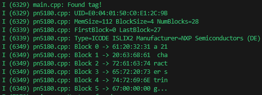
The response from the PN5180 will contain a byte of response flags and either one byte of error code or all the data that was requested. Most of these errors relate to whether the card is locked with a password, and the rest occur if sending an invalid response. To mitigate the chance of an invalid response, the command payload is checked for correct parameters before sending it out. This prevents unnecessary communication from occurring which would waste microcontroller resources.
This command is especially useful when performing an inventory command for all tags since each tag detected needs to be read afterwards. I took time to implement the read multiple block command in Arduino and share it on the same pull request from before, since these two commands go hand in hand.
Error Handling
I can’t be present at every location where these devices are installed. In order to have the best chance at diagnosing a problem if one were to occur, I need the library to spit out useful and specific error messages pinpointing where in the execution the issue is occurring. A client stating “card no do good” is not as useful as “the screen says Error - 0x6C” which I can use as a reference to discover the point of failure.
uint8_t* errorStack;
uint8_t errorCount = 0;

void functionA(void){
  bool success = functionB();
  if(!success){
    printError();
  }
}

bool functionB(void){
  bool success = functionC();
  if(!success){
    errorStack[errorCount] = errorCodeB;
    errorCount++;
    return true;
  }
  return false;
}

bool functionC(void){
  esp_err_t success = hardwareFnc();
  if(ESP_OK != success){
    errorStack[errorCount] = errorCodeC;
    errorCount++;
    return true;
  }
  return false;
}
I went with a technique, which probably has a proper term that I do not know, called error stacking. Every point of failure in each function has its own error code, and each function returns in a way known to the parent function as a failure. Each instance of a PN5180, when running into an issue, keeps an array of these error codes as it propagates back up to the first function, and these error codes can print human readable strings when called by a “printError” function. Once read, the errors are cleared.
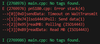
Error handling is a long and tedious procedure, but never forsake it when implementing code in remote locations. The easier it is to remedy an issue, the happier the client will be!
Program Structure and Simplification
All of the functions I need to implement to perform reads and writes on my RFID cards are done! There’s one problem though; in order to implement the library in its current state I need to call several functions, and call them differently depending on what I’m attempting to interface with. On a project-to-project or prop-to-prop basis, this quickly becomes a labor consuming issue.
pn5180.init();

for(;;){
  printf("The reader sees %s", pn5180.data());
  // Do other things...
}
The ultimate goal here is to make the implementation of the device as “no nonsense” as possible. When I use the PN5180 in my code, the goal can be reduced to a single action: read a tag. I perform actions unrelated to the library afterwards. Therefore we need a single, catch-all “read the tag” function that handles everything else behind the scenes.
There are 3 modes to implement:
- Read tag - Read whatever tag is present on top of the reader and expose it to the program to act upon
- Read multiple tag - Read all available tags on top of the reader and expose them to the program to act upon
- Write tag - The data passed to this function is written to any tags found by the PN5180
For a read tag function, I call a void function which goes through each programmed card protocol until it finds a card, records the data in a card struct, and can be looped indefinitely.
bool foundCard = lookForISO14443();
if(foundCard){
  readISO14443();
  return;
}

foundCard = lookForISO15693();
if(foundCard){
  readISO15693();
  return;
}
For a read multiple tag function, I do the same thing, but this time continue looking for cards and return any card found in each protocol.
uint8_t* iso14443Cards; // Raw data returned from ISO14443 Select
uint8_t* iso15693Cards; // Raw data returned from ISO15693 Inventory
uint8_t totalCards = 0; // Running tally of detected cards

uint8_t foundCards = lookForMultipleISO14443(iso14443Cards);
for(int i=0; i<foundCards; i++){
  readMultipleISO14443(iso14443Cards);
}
totalCards += foundCards;

foundCards = lookForMultipleISO15693(iso15693Cards);
for(int i=0; i<foundCards; i++){
  readMultipleISO15693(iso15693Cards);
}
totalCards += foundCards;
Write tag accepts data as a parameter, and writes the data to any card present regardless of protocol as well.
bool foundCard = lookForISO14443();
if(foundCard){
  writeISO14443(data);
  return;
}

foundCard = lookForISO15693();
if(foundCard){
  writeISO15693(data);
  return;
}
When the client, or myself, needs to create tags by writing data to them there are two options: implement a “write” mode or have a tag writer handy that is independent of the reader. Having a write mode would be cheaper, but annoying to train a revolving door of employees with. A dedicated writer in the office independent of any running operation seems better, and creating a write mode for an RFID that is physically inaccessible without deconstruction is not a good pitch to clients. The task of writing and reading can be split.
The main challenge for reading tags is the different data structures associated with each card. Reading 16 bytes from a Mifare block is fine, but an ISLIX tag only has 4 bytes per block and would never provide the same information. The solution is to continue reading blocks until the necessary data has been read, but how do we program it to know when to stop? If we’re looking for a 21 byte pattern, that doesn’t divide evenly with those two block sizes either.
bool flag_stopChar = false;

uint8_t block = 0;
while(!flag_stopChar && block < numBlock){
  const char* data = readBlock(block);
  for(int i=0; i<strlen(data); i++){
    if(!data[i] || isprint(data[i])) flag_stopChar = true;
    readableString[i] = data[i];
    block++;
  }
}
The approach I took was to write data to each card in the form of a string, and end the relevant data written to each card with ‘\0’, the null character. Now when reading each card and storing information, I can loop until I hit the null character, record the null character, and stop. Then when the data is requested by whatever program needs it, a properly terminated string can be retrieved. As insurance, I have the write function completely wipe out extra data with null characters when writing data to it.
Now when embedding a card or tag into something like a Jack of Spades, I can write “Jack of Spades” to the card and the program will return “Jack of Spades” when reading it. Human readable and no nonsense; pretty slick!
SemaphoreHandle_t pn5180_task_sem = xSemaphoreCreateBinary();
QueueHandle_t pn5180_task_queue = xQueueCreate(1, sizeof(uint8_t));
xTaskCreatePinnedToCore(pn5180_task_sem, "RFID", 2048, NULL, 0, NULL, tskNO_AFFINITY);

static void ctrl_task(void *arg){
  static const char* TAG = "RFID";
  static uint8_t task_action = 0;
  const char* lastData;
  xSemaphoreTake(pn5180_task_sem, portMAX_DELAY); // wait for main() to complete
  for(;;){
    // Attempt to pull task from queue
    bool success = xQueueReceive(pn5180_task_queue, &task_action, pdMS_TO_TICKS(10));
    if(success && task_action){ // If we have a task, copy and send our current data over
      memcpy(lastData, data, dataLen);
      xQueueSend(main_task_queue, lastData, portMAX_DELAY);
    }

    readData(); // Continue looking for data...
  }
}
FreeRTOS is the main driver to implement this method. Before compiling, I simply have a checkbox to enable the PN5180 library. If checked, additional options appear to select how many readers are connected, what mode they are in, and which predefined set of pins and SPI bus to attach them to. Defines scattered throughout the library will optimize the compiled code based on which options are selected. The library automatically creates a FreeRTOS task dedicated to the readers, performs all of the initialization procedures, and handles all the necessary functions to get the data without any extra code cluttering our main function. All we need to do is ask for the data with a single function when we need to use it.
Physical PN5180 Design
With the programming in an acceptable state, the next consideration is how to install these devices. When purchasing these, they come on a PCB with no header pins included. I need to interface 9 wires from the PCB to the board I plan to control the PN5180 with, and I need to come up with a mounting solution for the device.
Plug ‘n Play
Based on my past builds involving RFIDs, I know creating cables or stripping wires for each of these modules is going to be too time consuming. It’s a lot to ask even for terminal block headers. Put 5 of these in a board, and you’re looking at 90 connections to make.
I need to come up with a way to make one connection and go for my installs. The question then is: what type of plug needs to interface with this device? SPI limits how long I can run the wires, and for now I don’t plan on integrating a dedicated microcontroller and CAN/RS485/RS232 interface into every PN5180 to make long distances happen, so that narrows the choice down to plugs with at least 9 pins and affordable cables that can be purchased in long lengths within SPI specification.
A cheap and effective solution would be ethernet cables… if the reader didn’t need 9 connections. Just one wire away from being a good answer!
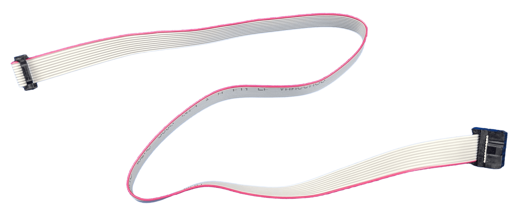
I ended up settling on IDC cables. They’re easy to source online, can be purchased premade at the lengths I need at a reasonable price, and if I want to do it even cheaper I have the option of crimping these cables myself with a reasonable investment in a ribbon of cable and IDC crimpers. Crimping the cable involves pulling apart the chunk of the ribbon needed, sticking the ribbon in a plug, and crimping. No individual wires to handle; a ribbon is one solid piece. The cables are rated for currents upto 2A, which is well beyond the 250mA maximum the PN5180 pulls. As an extra bonus, the cables are thin and low profile, making them easier to route through tiny nooks and crannies.
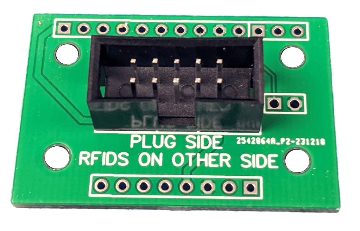
In order to connect an IDC plug to the PN5180, some sort of adapter needed to be developed. I designed a small PCB for this purpose. Each board is soldered directly to the PN5180. For a board connecting with an IDC plug at the other end, it simply needs to match the pinout. I made sure to add big printed letters on each side stating which side to solder the plug and PN5180 into as well as the orientation. I know what autopilot is capable of.
Modeling and Making
Next I needed to develop an enclosure for the whole assembly. Although these devices are going to be installed inside things and out of reach from any tampering, a case is going to add an extra layer of durability, add some presentation and identification, and provide a way for me to design an easy mounting solution for the device.
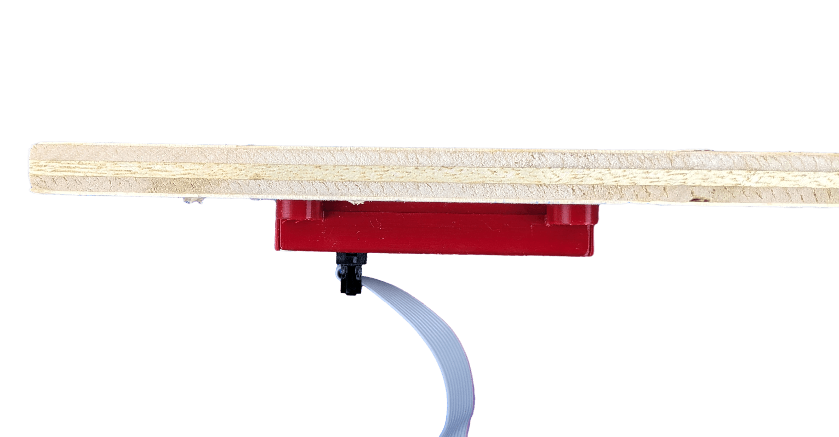
I have a 3d printer and modeling experience, so we developed something nice for this small assembly. Both the PN5180 and IDC adapter were modeled as accurately as possible to ensure the case would be correct. I made tabs on the side which slot for #6 flathead wood screws, allowing them to be flush with the case. The pcb of the PN5180 and the adapter are secured vertically by grooves in the case, and horizontally by the plug extending out of the case from the bottom. The top shell clicks into place with some annular snap-fit joints in each corner. Details were added to the bottom to mark the center of the read spot of the PN5180 for alignment, and device name and logo went on the top.
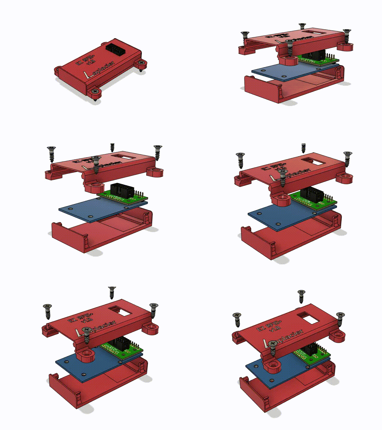
It took one test print to dial in all the tolerances and small mistakes. Print number 2 did the job perfectly. The annular snap-fit joints were working on the first print, but I was concerned about them surviving repeated stress with how thin they were. I ended up tripling the width of them and increasing the length of the case by 5mm to accomodate the increased size.
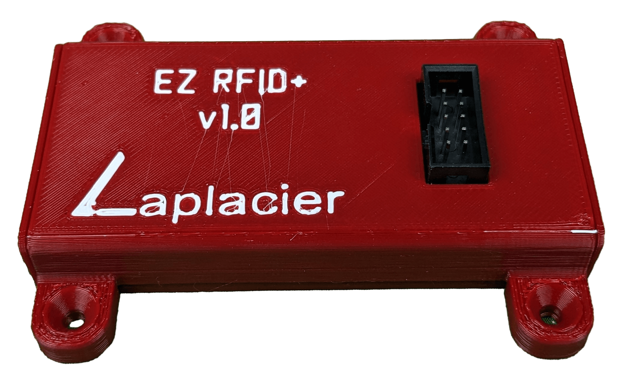
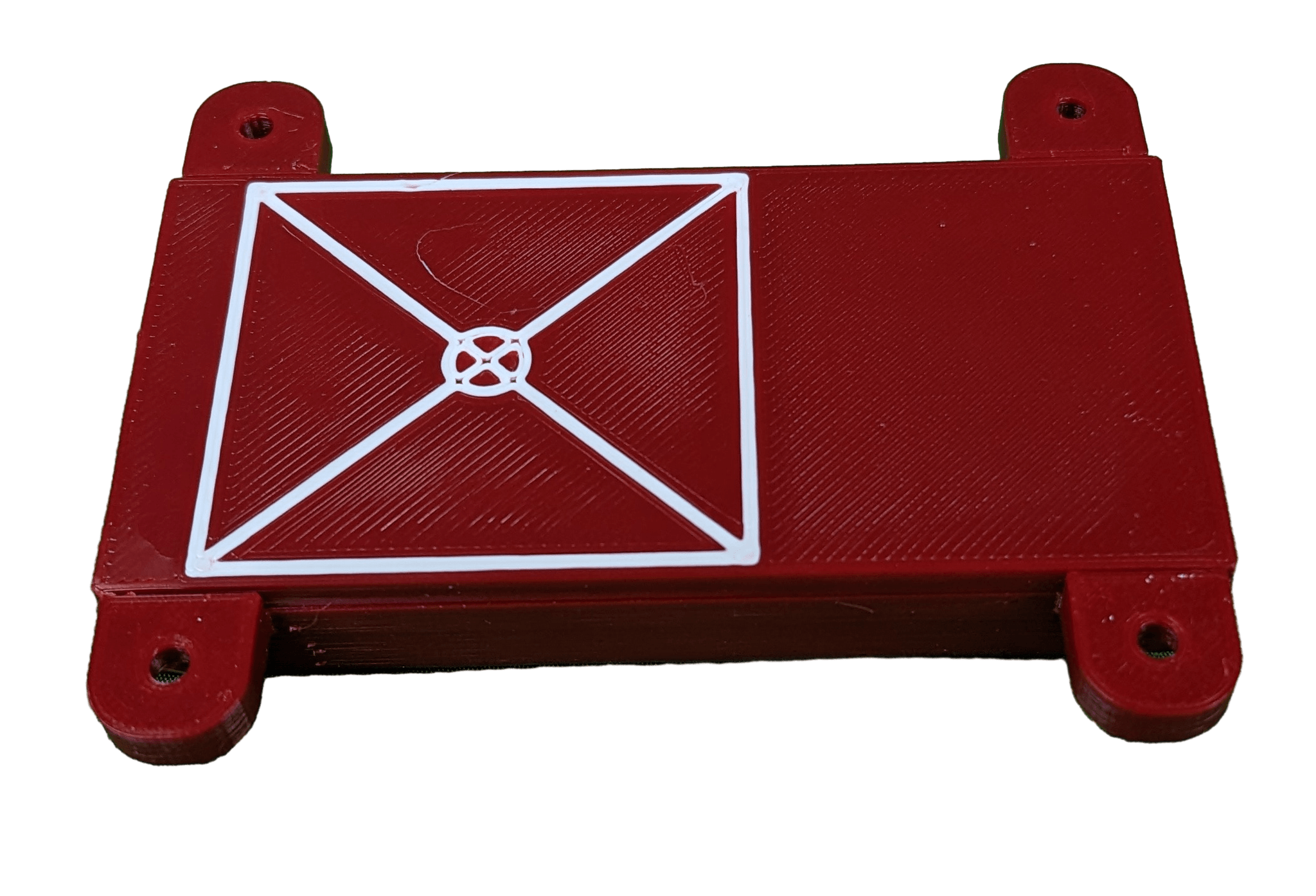
Printing the cases can be performed passively. The personal time invested in printing batches of cases, assembling each RFID module with IDC adapter, and snapping the case on each one is about a 5 minute job per module, ignoring set up time. This is reasonable considering I can set aside time to put a full inventory of them together in one short go and have enough ready to complete multiple rooms. With the way the library is structured for the use case, programming time is negligible as well.
Comparisons to Existing Implementations
They Read the UID
The common implementation for RFIDs used in basic prop detection is to check the UID of the card. Once the UID is found, any further actions are ignored and the UID is passed as the identification of the card to the program. UIDs are unique, and are not shared between cards, ensuring no two cards will read the same on a reader. This is easy to implement, since the structure of the card memory no longer needs to be taken into consideration. All of the public libraries for various RFID readers implement this feature by default. There are problems and limitations when choosing this solution.
If a card is ever lost, no cards are going to substitute the lost card. UIDs are unique. The consumer modules I have possessed bypass this restriction by implementing a “programming” mode into their readers. Once activated, a user simply needs to place a new card or multiple cards on top of the reader to store them as “correct”. These UIDs are typically stored on EEPROM inside the microcontroller or an external IC. The activator for this mode is either an external button or a “master” RFID card that the reader is hard coded to recognize.
An external button to enter programming mode requires an employee to have access to said button. Your options are to have a button out in the open a guest could mistakenly find, or open the prop containing the reader to access the button. Neither of these options are good for the business. The master RFID is even worse. It solves having to access the reader physically to reprogram it, but if the master is lost, the RFID reader is a brick. Better hope the working tags stay working and never go missing. As an additional downside, I have handled consumer modules that do not save any UIDs after a reboot due their internal EEPROM failing. No writeable storage leads to a bricked RFID as well.
These are problems I ran into through my time in the field, and development was spurred through these shortcomings. Taking the time to implement a proper method to read the data on the cards solves these issues.
We Read the Data
Data written to the card is not unique, but lack of uniqueness in this setup is user error rather than a limitation; don’t write the wrong data to the wrong card. Data written to the card can be meaningful and directly relate to the object the card is placed in. A Jack of Spades can read “Jack of Spades” directly without constant remapping of values when cards are replaced. An external device can also prepare a replacement card without ever having to enter the room. If the card writer is ever lost, nothing is bricked. Any RFID reader can perform the same write function. The solution to each reader can be hard coded without any issues, eliminating the need to perform constant writes to microcontroller memory and wear it out. An employee can sit in the office and make as many writes to an RFID card as they’d like since their read/write durability is phenominal. They’re also negligible in price to replace.
Operator Feedback
Sending data pertaining to a sensor in the room is critical for ease of operation. Employees are not going to be able to spot everything in the room off of a small camera pointing down from the ceiling. They also won’t have x-ray vision to see inside the props to inspect sensors inside while the room is in use.
Systems that send information about the room back to the operator are highly sought after. They reduce mistakes, improve troubleshooting, and provide a better experience for both the customers and employees. RFID readers implemented in rooms with these systems often fall short in this regard. With the UID reading method it is technically possible to provide all the necessary information, but it is rarely implemented due to the difficulties surrounding the UID method. A UID string by itself means nothing to the operator. Something in the middle needs to translate the UID into a meaningful string describing the prop associated with it. To make this happen with UIDs, ALL RFID readers need to be aware of all cards associated with the room. That’s not practical when they frequently get replaced.

Instead, most of these devices abandon sending useful information to the operator altogether, and only send a true for correct, and false for not correct. Is that the King of Hearts being placed where the Jack of Spades is supposed to go? Is anything even on the RFID reader to begin with? Unless you have eagle eyes and the customers aren’t blocking your view, you’ll never know.

Reading data on the card does not have this limitation. The data is already human readable. The reader no longer needs to concern itself with the information past the correct answer. Regardless of what it reads, it can send data straight to the operator first and determine correctness after. The operator sees Pot of Flowers pop up where Jack of Spades is supposed to be. They now know a customer put the pot where it clearly shouldn’t be and hints can be properly addressed. When a card is lost/broken and replaced, nothing needs to be reprogrammed to continue receiving useful information.
Features to Implement
The RFID module is in what I could call a “minimum implementation to achieve best result” state. There are some features missing and unsupported cards, but the critical features are done, the commonplace cards are supported, and all of the issues I experienced on the field with competing modules were ironed out.
More cards can be acquired, tested, and integrated into the library that the reader supports. Some cards are out of scope, like ICODE DNA cards that are a generous bump in price to provide extra security, but NFCs are a good candidate for being integrated into the library. I’m also interested in trying out some ISO18000-3M3 cards, the most modern protocol supported, to inspect their performance.
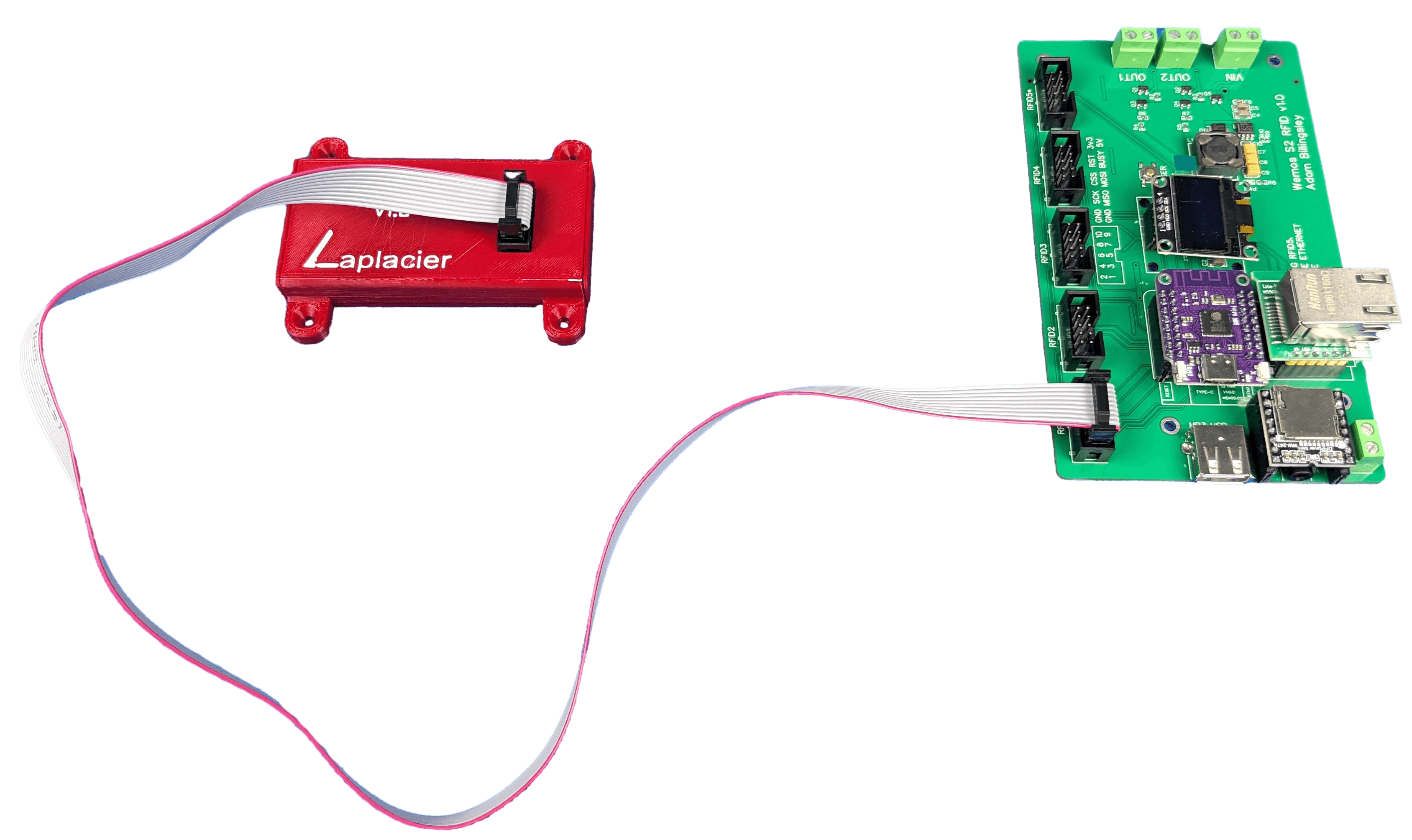
SPI communication is spec’d to run up to 10 meters, but whoever hit the number had some nice hardware. In my experience, implementations involving SPI communication start to struggle with occasional errors around a meter away from the board. Increasing the distance requires lowering the clock speed, an LTC4332 built in on both sides (SPI range extender), or a microcontroller placed near the reader. Lowering the clock speed doesn’t get you too much further in exchange for significantly slower operation. Plug ‘n play LTC4332 boards require a slower clock speed to operate and are not cost effective. That leaves the best option: interface a microcontroller with a reader directly and add CAN/RS485 to the board or communicate wirelessly over wifi/radio. Of these options, wifi would be the easiest to implement in my ecosystem. I’d still need to run power to the board, so integrating regulators for 5V and 3.3V into the design for one reader would push the price up. It’s a bridge I’ll eventually have to cross, but long distance implementations are rare. I’ll wait until a use case appears first.