· Products · 20 min read
Prototyping: Wemos D1 Prop Board
Planning and prototyping a powerful, silent, quick install prop board

One of the biggest challenges when installing props is time. When working on a remote location, each day required to complete a room is a day of travel costs and labor. Cutting down this factor will save you money and allow you to offer more competitive rates.
For each build, I spend the most time on site with electrical and programming tasks, such as wire drops, terminating stranded wire with ferrules/crimps for safety and professionalism, retrofitting the hardware to existing props, tuning the programming to meet the design criteria of the prop, and setting up a local backend for the customer. Put together, all those tasks used to take me several days. After completing three rooms back-to-back this way, I worked on solutions to maximize time efficiency.
The common prebuilt solutions I researched online did not offer the level of customization required for many of my builds. All of my builds require more than “just a button and a switch” to perform their task. Of the solutions that offer more, their cost is prohibitively expensive for what they offer. It should not cost upwards of $600(!!) in hardware, no power supply included, to make a single prop read 4 RFIDs and send the data over the network, which is a commonly requested configuration.
Looking at these offerings, I came to the realization that there is a large void in this market for an affordable system that can address these issues. I needed a board that could perform all of my common prop programming tasks, be installed and retrofitted quickly, and be created at a reasonable price.
Identifying Needs
The props requested by escape rooms have some variance from person to person, but ultimately the electronics of a prop for a customer can fit into the following template:
Boolean sensors
The most basic form of sensor is a boolean; which is any sensor indicating either an on or off state.
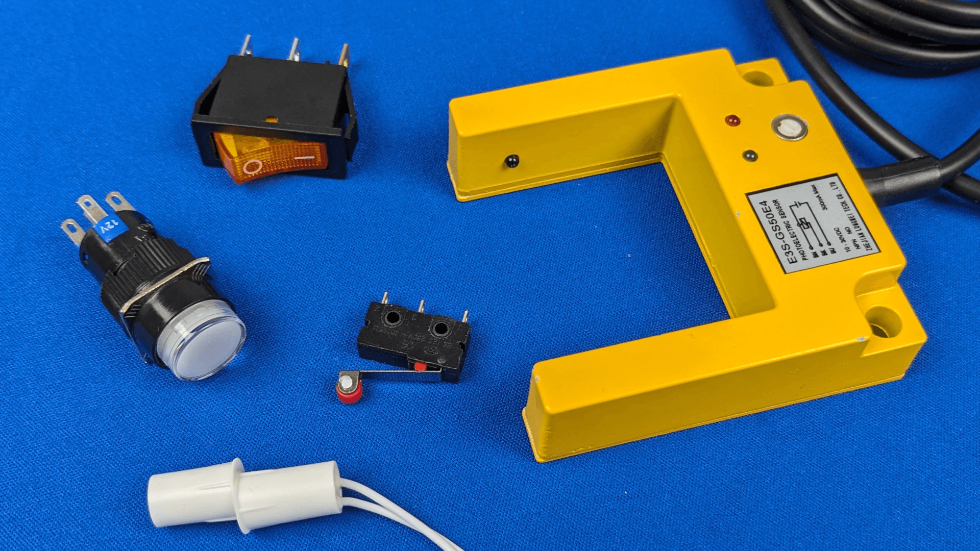
Sensors fitting this category include buttons, beam breakers, reed/hall effect/magnet sensors, switches, and more. Any sensor classified as boolean cannot provide any additional meaningful information aside from a simple “yes” or “no”. A sensor with a “yes” state that relies on additional information is NOT a boolean sensor.
Analog sensors
Some sensors in the field depend on analog data to perform a task. The desired result of an analog sensor may be similar to a boolean sensor, the two devices achieve this state differently.
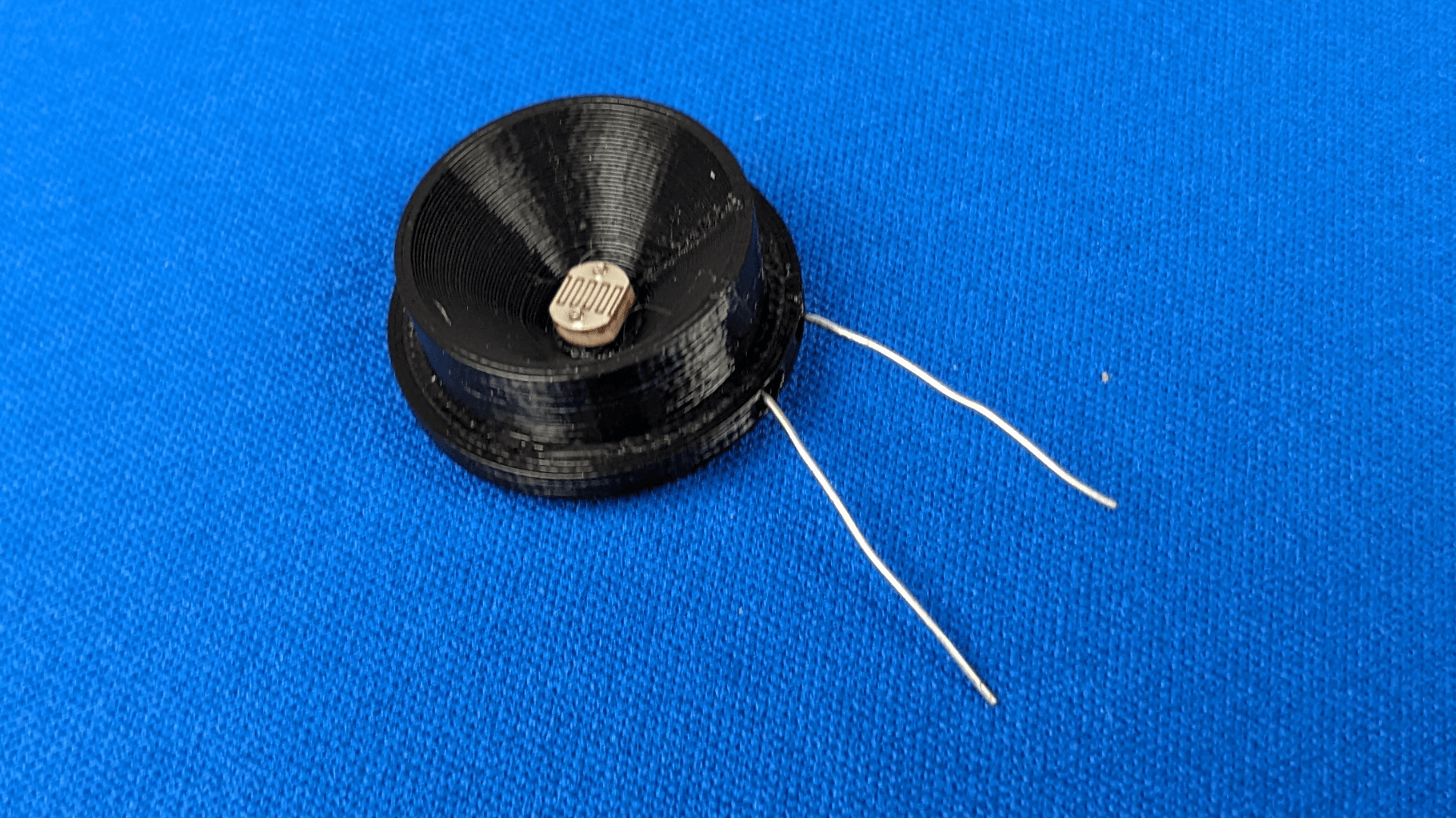
A photoresistor, or light sensor, detects the surrounding ambient light which can transmit a large range of values to define the current light intensity. A knock sensor detects vibrations of the attached surface which can be measured via peak amplitude over an analog signal. The desired condition requires measurement of an analog signal value. The value can also vary greatly depending on the environment it is installed in, which requires calibration on installation and recalibration after install in some cases.
Encoders
If there’s something to turn, an encoder is behind it. Potentiometers can also be used to detect turns, but they have hard stops, and guests will end up destroying the potentiometer without significant construction in place to prevent it. Some props implement reed switches behind their turning apparatus to detect correct position, which is valid, but makes determining any position outside of the correct one complete guesswork on the operator side. Only an encoder can provide the full story of what is happening when rotating a device.
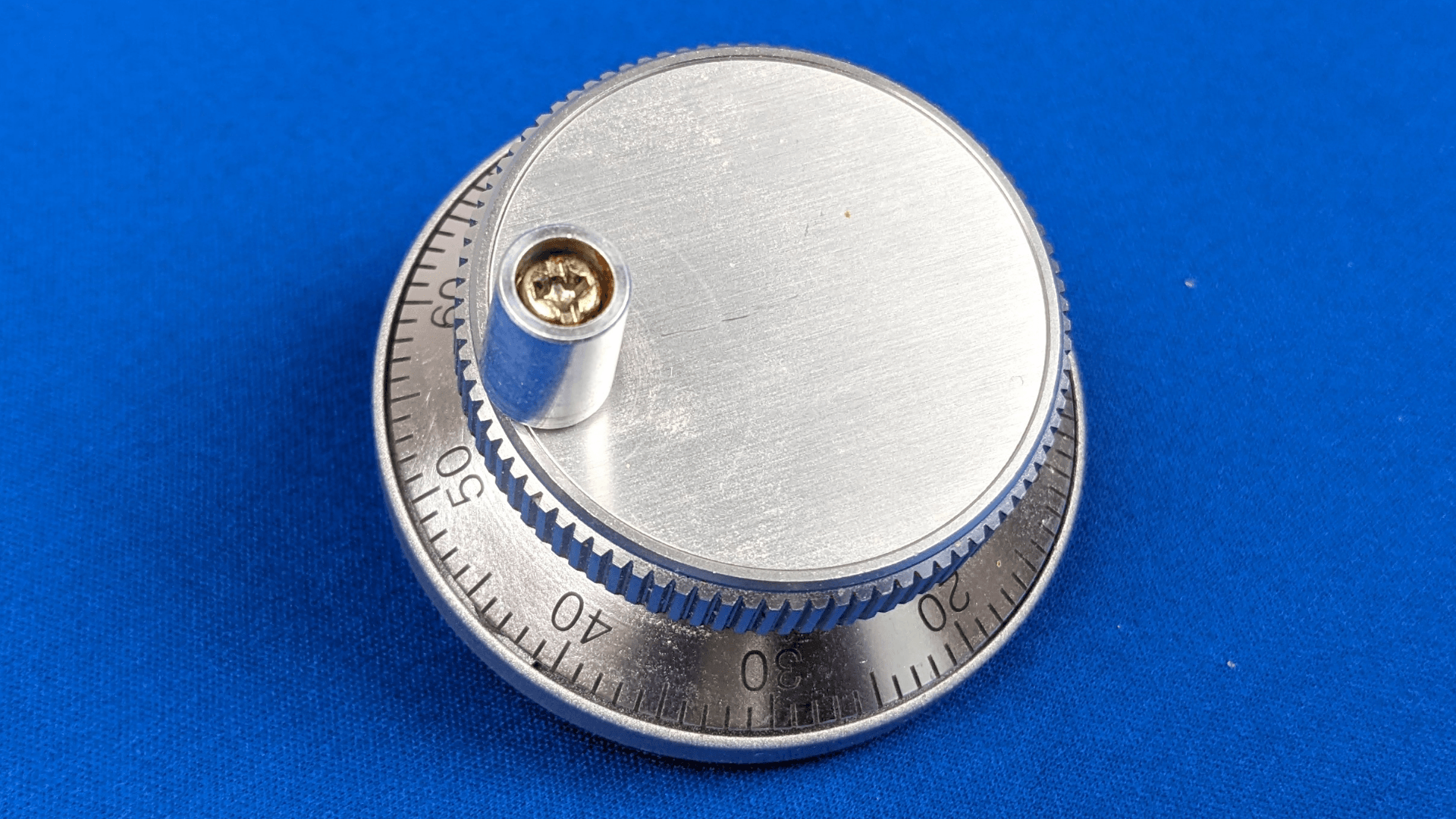
Encoders come in different flavors but can be boiled down to 3 types: absolute, incremental, and z-phase incremental.
Absolute encoders contain mechanical parts that allow them to know at what angle they are located at all times. They are the easiest to implement, but are also prohibitively expensive.
Incremental encoders, the most common and cost effective type, send two pulses out of phase of each other on each rotation. A controller will have no idea where its position is on power on, and can only detect position based on the position after power on. Puzzle designs must take this into account, or have the ability to “home” or “recalibrate” an encoder.
Z-phase incremental encoders are similar to incremental encoders but include an extra wire. The z-phase wire is high when encoder reaches its mechanically defined 0 point and low when not. When implemented correctly in programming, a z-phase encoder is just as effective as an absolute encoder and much cheaper. An operator only needs to spin the encoder once on boot up to prepare the prop.
Audio
Audio is an important tool to immerse guests in the experience and is always requested. Audio needs to occur at certain times or play based on certain sensor triggers. By a wide margin, the most cost effective way to implement audio into props has been to slap a DFPlayer Mini inside. It includes the ability to play tracks, loop tracks, output DAC (headphone jack), and output audio off an internal amplifier which allows speakers to be plugged in directly to this device. Files can be played off the SD card slot mounted on the device. It can also play files off a flash drive, of which not a lot of people are aware.
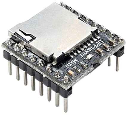
While effective for several cases, I am finding myself continuously limited in what I can offer with audio when using a DFPlayer. Those limitations and some caveats when using the DFPlayer are detailed later on in this post.
Power Switches
When most designers think of switching power on or off, they immediately gravitate to the “blue clicky box” relay that is ubiquitous throughout circuit designs, and that is for good reason. A standard opto-isolated relay module can handle any switching task from logic signals all the way up to 220V mains power and currents from a few milliamps up to a whopping 10 amps!
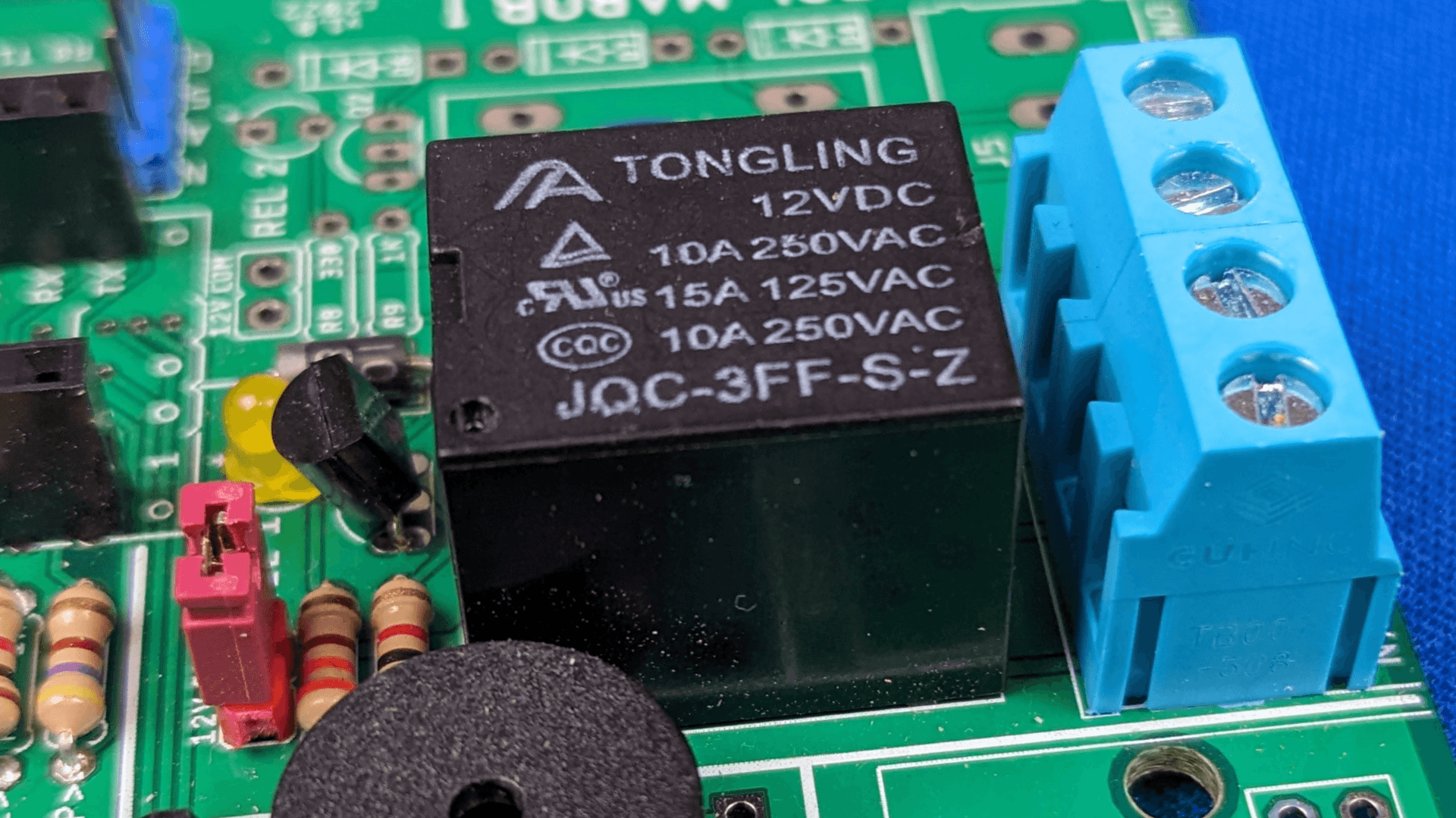
There’s no other module out there that can provide that level of flexibility at such a small price point. It can also be found anywhere and everywhere for sale from many manufacturers and in several configurations. Every single commercially available prop board I viewed offered these as built-in output modules.
However, one property of the module makes them problematic for installing inside props: the mechanical clicking noise from activating a relay. The sound of a relay click is impossible to isolate effectively at close range.
Using a relay module means providing a guest with an uncontrollable audio cue for a prop trigger. Since the relay module is a standard in nearly every escape room, customers have become conditioned to manipulate a prop until they can hear the click sound. It really takes away from the immersion and experience of the game.
Looking back on the various apparatuses I’ve connected to relays, I’ve connected them to digital logic signals, various locks, light strips and main power devices. For digital logic, other than a single case of manipulating a proprietary video player on site with a nonstandard voltage level, there have been cases where I substituted an output for an input in a pinch. Having a relay built in for this case does not make sense. For controlling mains power devices, a relay will be mandatory, but these cases are rare enough to justify their exclusion from a main board design.
That leaves locks and led strips. I would estimate around 95% of the outputs used by the props I’ve implemented involve these two devices. All of the locks I have interfaced with up to this point operate at 12V or within a range that includes 12V. While led strips operate at a couple voltage levels, they’re cheap enough to consider replacing for compatibility if they already exist in a prop and they aren’t 12V.
With this reasoning, it becomes feasible to create a solid state mosfet circuit for output switching. I can isolate the logic signal per usual, but use a combination of power mosfets to deliver 12V power instead of a relay. Power can be switched like a relay, but be completely silent. No more audible clicks coming out of the board inside the prop! For the niche cases where a relay module is required, it can be included as a separate module.
And if you’re thinking to yourself “why don’t you just install the board somewhere outside the room where the customer can’t hear it?”, consider the amount of additional labor and wiring required to relocate a controller with 10-20 sensors on board and run the wire neatly. While having a “master control panel” where you keep every board sounds great on paper, it makes the price and installation time significantly higher. The purpose of this design is to make installation faster, cheaper, and easier. The shortest wire run that doesn’t dangle in the air is the cleanest and most efficient wire run.
Minimal Dependency
The controller needs to rely on other hardware aside from its own as little as possible. If communication between devices fails due to issues outside of the prop’s control, such as the Internet being unresponsive or an entirely different prop malfunctioning, it must be able to perform its own task regardless of those issues.
User Interface
Every escape room needs an effective user interface that the operator can use to monitor the room. The interface needs to provide as much information to the operator as possible to reduce uncertainties about the state of props and identify issues when they arise. Paradoxically, it also needs to provide as little information as possible to reduce visual bloat and make finding information easier to reduce the amount of training required to operate the interface. Both of these states can be achieved with a carefully designed front end, but in either case it still requires as much information as possible to be sent. ALL data relevant to understanding the state of the room must be relayed to the interface in an easily digestible format. The interface must also allow the operator to control the necessary elements of the room when help is needed.
I’ve provided front ends through Node Red and Homeassistant. Node Red provides a more industrially sound solution that is lightweight and can live in a box without any maintenance. Once a Node Red dashboard is created and operating, there’s not much that can go wrong and I can rest easy.
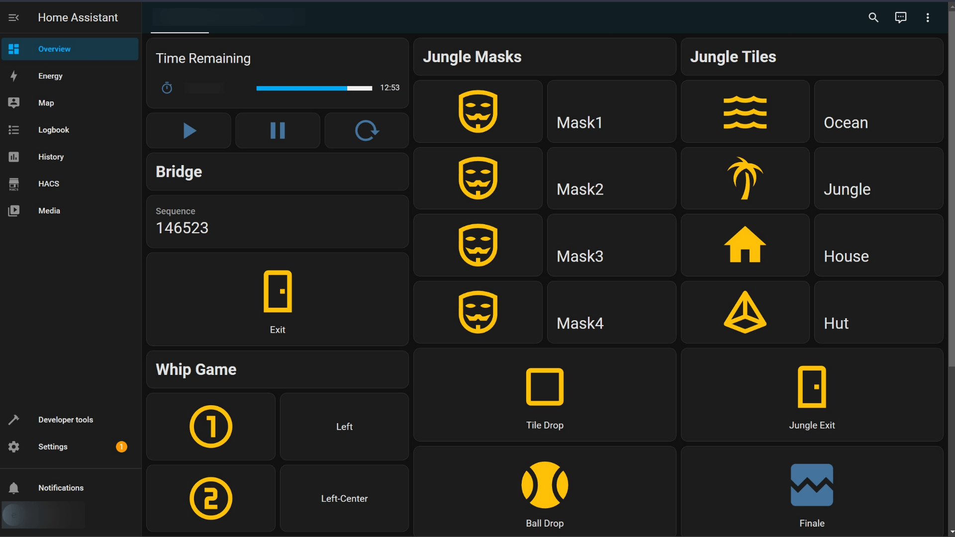
Homeassistant is a community driven solution intended for controlling smart homes, but works equally as well for controlling escape rooms since they operate identically to a smart home. Homeassistant has a more advanced and appealing front-end due to the massive open source community it commands. If there’s a question on how to design something on the front end, between the monolithic amount of well documented instructions and amount of community support it’s hard to not find a solution. However, it comes at a cost. The Homeassistant community/team adds and fixes all the latest smart home appliances, pushes updates to the user constantly, and each update has no obligation to prevent your system from being broken. There’s also a lot of bloat under the hood for running a smart home that an escape room does not necessarily need like location tracking and energy monitoring. However, those features could be utilized to automate the building on top of the escape rooms, but I haven’t pushed that far yet.
Between the two I prefer to install Node Red based on the reliability factor, but the level of customization that Homeassistant provides always wins the appeal of the customer. Who doesn’t want to have an open source system with so much documentation available that they can add tons of features to it easily by themselves? It’s been so popular that it actually influenced programming decisions on my end to make them easy to integrate into Homeassistant.
Circuit Design
For my first design I did not want to try to tackle every problem at the same time and attempt to make “the design” in one go. I designed a board around familiar microcontrollers and focused on a design that allowed me to test features and components without having to debug issues of uncertainty.
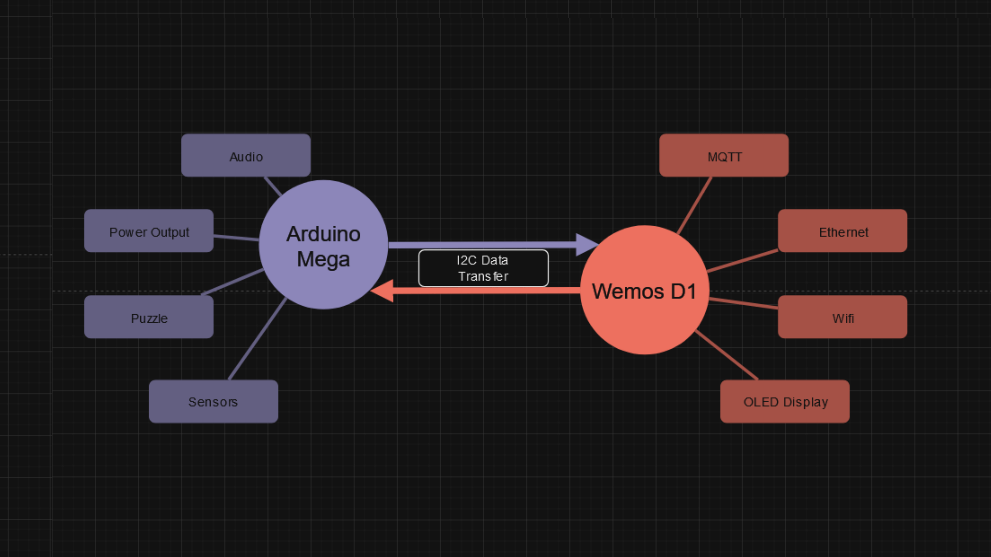
I based my original design for a prop board around an Arduino Mega and Wemos D1 microcontroller. The mega would be responsible for the puzzle and sensors, while the sole responsibility of the Wemos would be communication between the board and the rest of the building ecosystem. I tied them together via I2C communication and created methods to convert data traffic from Arduino logic to network logic and vice versa.
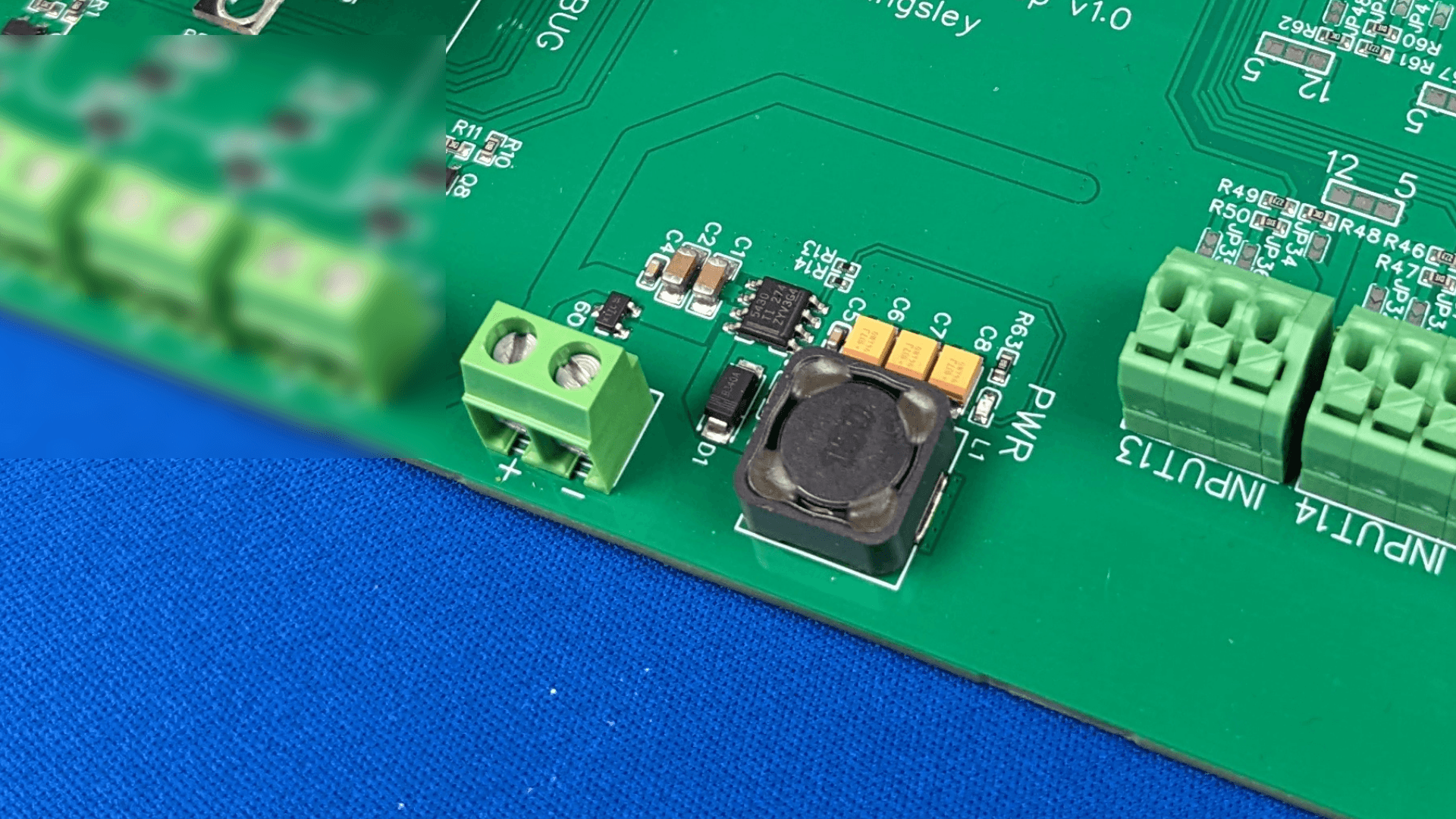
For board power I wasn’t picky; I needed to input 12V and output 5V to the board to power the microcontrollers, and the 3.3V regulated power pins on both the Arduino Mega and Wemos D1 would suffice for powering any 3.3V components on the board. I used a switching regulator from TI labeled as the TPS5430DDAR. It has a sufficient voltage range to account for voltage drop across longer power cable runs, I can bump up the input voltage a small amount to compensate since it operates on voltages upto 24V, and the external part count was low. I ran the calculations for the necessary circuit values such as DC resistance, selected external components to match, and made the external loops as tight as possible to increase the efficiency and reduce voltage ripple.
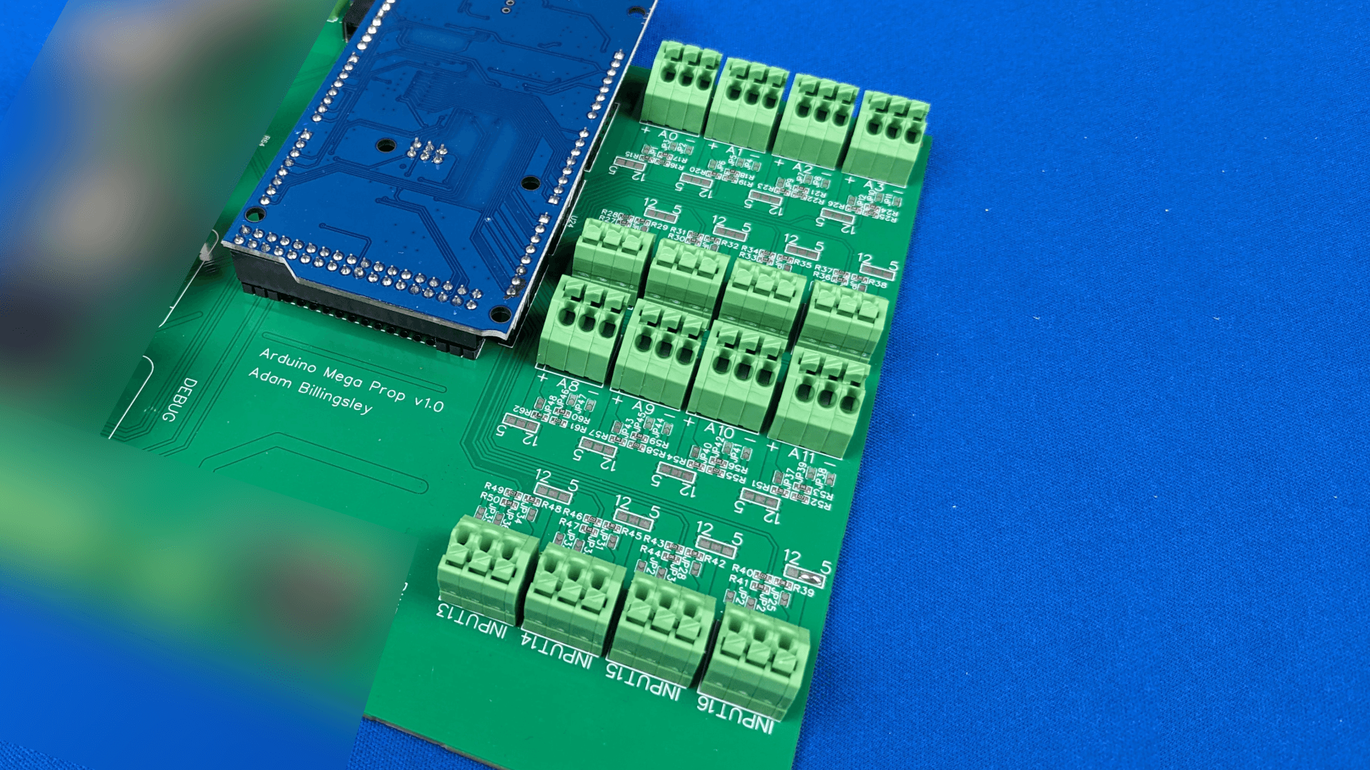
One of my personal struggles with installs involving consumer controller boards are the lack of ports for power and ground. Ports are removed to save space and reduce design complexity on the board, leaving it up to the user to implement their own breakouts for power and ground. Sensors and outputs do not operate off a single logic wire, which makes breaking out power and ground a necessity 100% of the time. Its inclusion would make the product infinitely easier to use.
Sensors all have their own voltage requirements, so I needed to be sure to implement a method to alter the voltage supplied to the sensor. I also needed to ensure the input logic voltage levels were stepped down to a safe level for the microcontroller. To accomplish this, I ran 12V and 5V power buses in front of each input and added a solder jumper which connected to the sensor power supply. Jumping one side connects 5V, and jumping the other connects 12V. The sensor logic is similar, but with a few jumpers placed in convenient locations and a resistor divider network to divide the logic down from 12V to 5V. I also included a 1M resistor with a jumper in case of a raw knock sensor, and a jumper for direct GPIO access in case an input needed to drive an output instead.
I wanted to make sensor connections more “plug-n-play” than regular terminal block headers while keeping the labor of terminating the wires of sensors low. To provide a wire to board connection to these inputs, I chose some spring terminal blocks. I can still utilize ferrule connectors for terminating sensor wires, which are quick and easy, and turn sensor connections into a push and release action instead of a slower, screw tightening action.
The Arduino Mega has a plethora of GPIO pins, but providing headers for all of the GPIO pins each with a dedicated power and ground would consume a large amount of space on the board. I chose to dedicate header space to all of the analog pins, limiting the input count to 16 while maximizing the capabilities of the inputs.
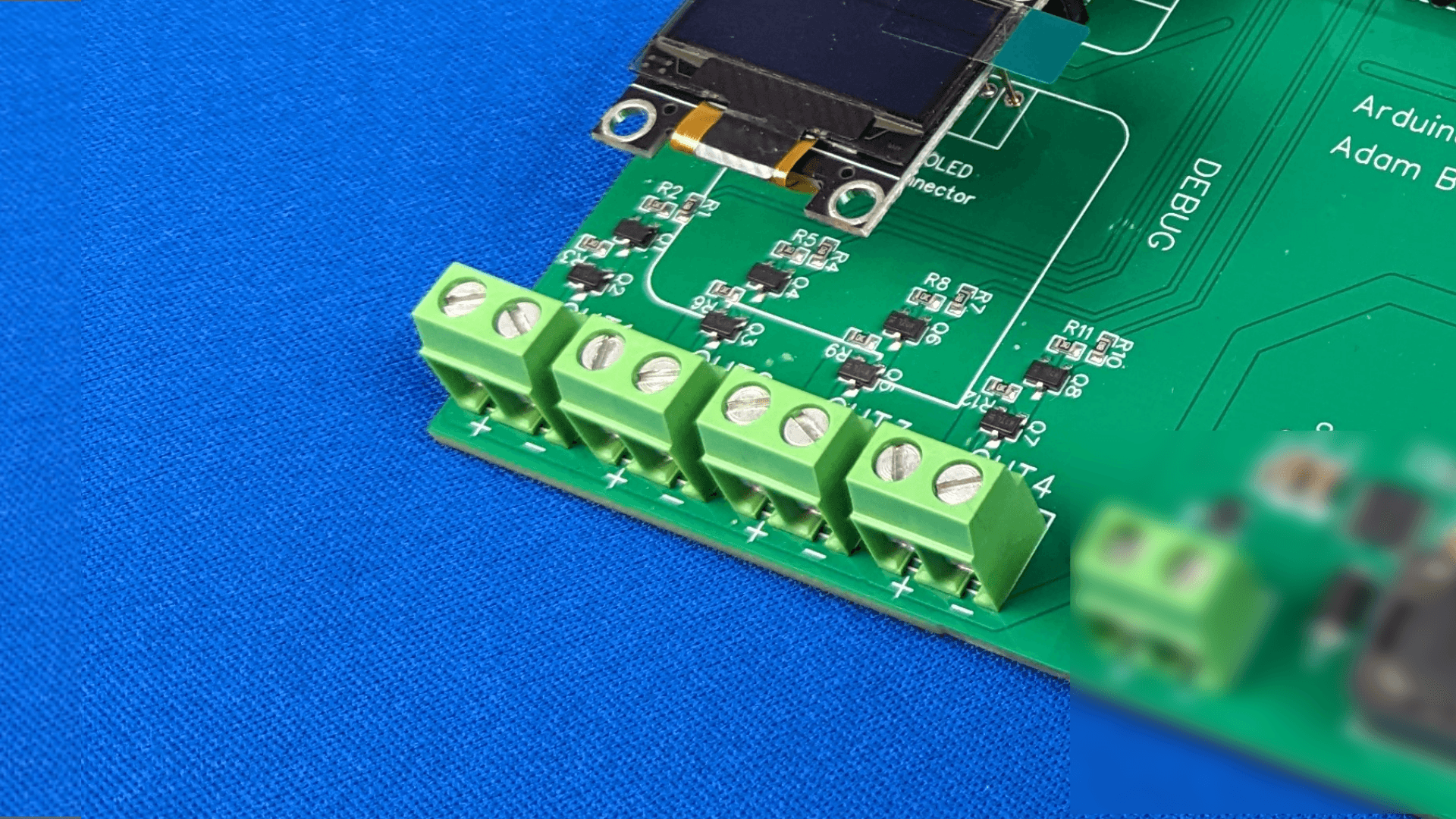
The outputs are toggled via a p-channel mosfet on the high side. That mosfet is toggled by an n-channel mosfet which provides 12V to the gate of the p-channel mosfet, and the n-channel mosfet gate is toggled by a GPIO pin from the Arduino Mega. An opto-isolator would have sufficed in place of the n-channel mosfet, but cost and spacewise the n-channel mosfet was superior.
The Wemos D1 has wifi capability, but wifi isn’t always an option for connectivity in an escape room. A wired protocol needs to be implemented for reliable connectivity.
CAN and RS485 are common industry standards for communication. However, these protocols require parallel connections to all connected devices and the parallel branch distance must be kept to a minimum, meaning the parallel connection is implemented directly in the board in most cases. Therefore a network of CAN/RS485 devices would require additional wiring and planning to chain the props together, due to a board needing to connect in series from the prop ahead of it to the prop behind it. The protocols can handle erroneous behavior in a board, but disconnection of any board will prevent the entire system from operating properly.
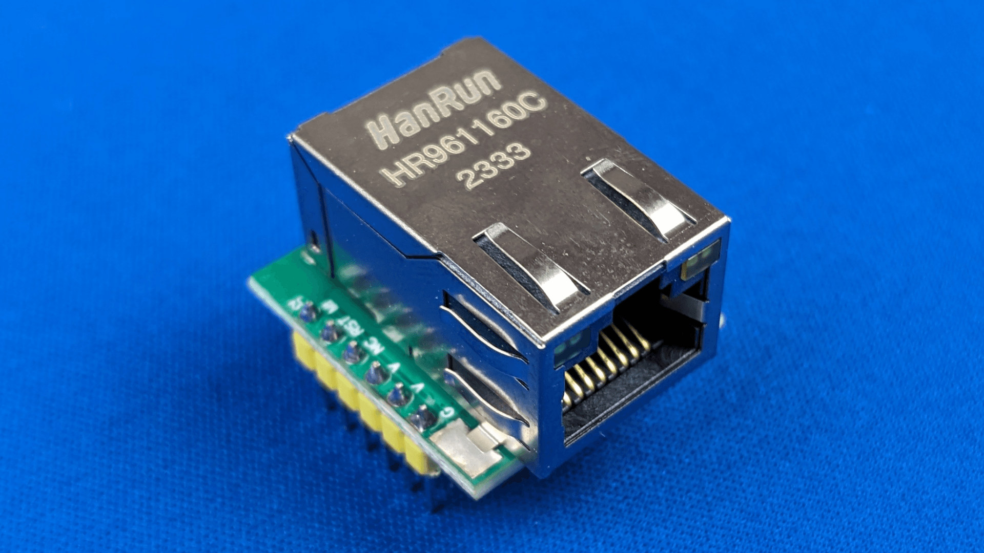
For those reasons, I chose to implement ethernet on the boards. There are a few easy to implement modules available, and I chose a w5500 module. Wifi and ethernet both communicate over the network similarly, so this also reduces the headache of creating data conversions and methods when sending data.
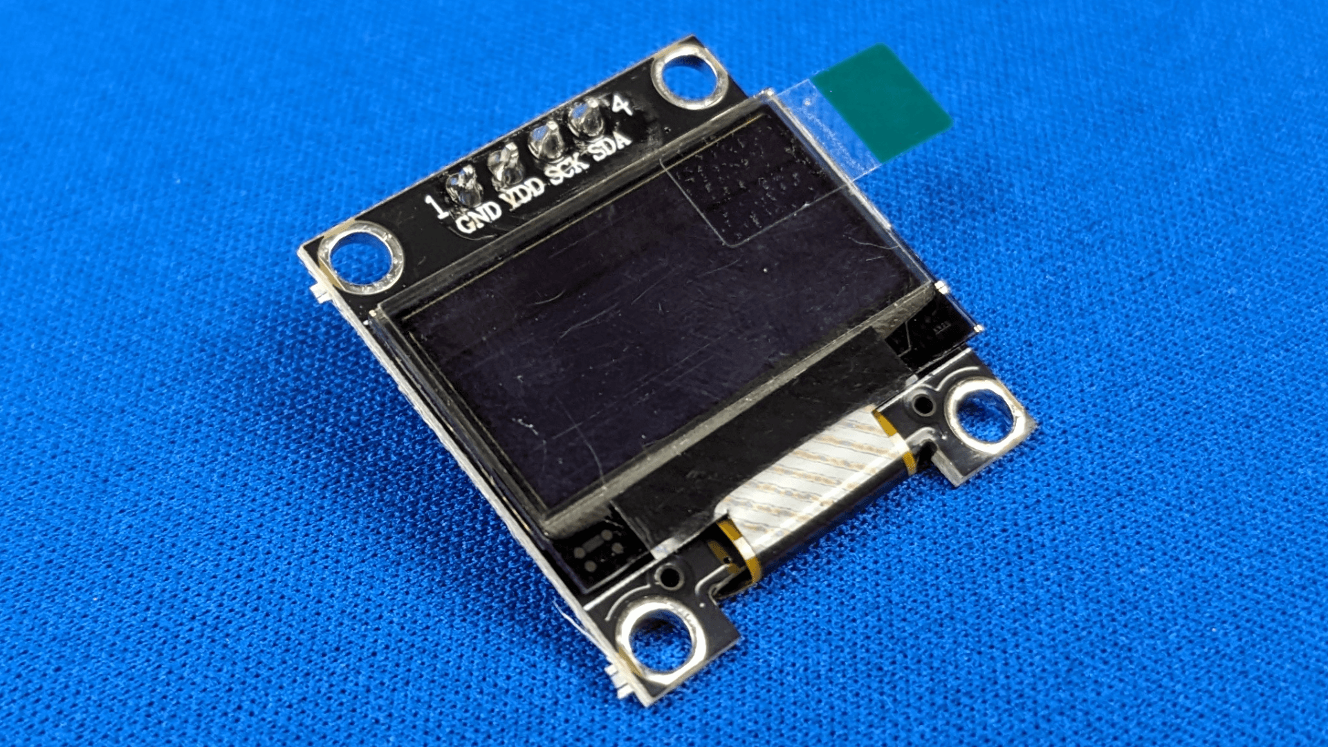
To relay information to the user, most boards use the approach of LED indicators with various blinks or colors to signal information. I wanted my information to be immediately discernible without the need to reference a manual, so I implemented a small OLED display. The display has enough space to display several lines of text and can display more by simply scrolling or overwriting. When other communication methods fail, a glance at the screen can relay the appropriate information quickly.
Putting it all together, I layed out the inputs in a symmetric array on one side, and placed the rest of the connections alongside the open edges of the board where they fit while making sure components that related to each other stayed as close together as possible. I also made the trace widths of the power busses generously large and overcompensated for their power and thermal requirements.
Programming
At surface level, the Wemos D1 handles all traffic leaving and entering the board and manages the OLED display while the Arduino Mega takes care of the puzzle logic and sensors. For each prop, the Wemos D1 is programmed with MQTT topics and channels related to each sensor and also listens for commands to manually change behavior. The Arduino Mega also receives a custom program that performs the necessary logic to operate the prop.
To simplify program planning, a common template that I adhere to is a state configuration, where the puzzle logic is defined by the current state of the prop. At minimum, a prop needs a state for playing the game and a state after the game is complete. I will refer to these as READY and WIN states. I also implement a RESET state, which assists a game operator in any manual operations such as placing physical items in locked cabinets, and sometimes I implement an IDLE state, which prevents the prop from being interactable until a condition is met. If additional states are needed to complete the logic, they’re wedged between READY and WIN.
With this system, I need to manage the following on a prop to prop basis:
- Add network credentials and MQTT topics.
- Define the sensors and peripherals in setup.
- Place any additional output peripherals (LEDs, etc) in an “off” state during RESET.
- Decide if IDLE state is required, and define the exit condition if needed.
- Define the “once on state” logic for each state.
- Define the looping logic for each state.
- Create the puzzle logic required to solve the game in READY and any additional interactive states.
- Define a method to manually return the prop to a READY/IDLE state after WIN if necessary.
The rest of the code remains static. Methods for interfacing with the audio, ethernet, wifi, and all of the GPIO assignments to each input are hard coded.
Performance on Site
This board ran a third of an escape room on one site, a prop consisting of 12 knock sensors in another, and two props on one board requiring 14 reed switches. In all of these cases, wifi connections were used to communicate. Both props ended up performing their tasks and running their puzzles with no issues. While installing these boards I made sure to take note of the improvements and pitfalls compared to previous installations.
Improvements
The electronics and wiring were more condensed, since everything needed was located on one board. Cable management was made simpler due to sensors funneling over to one side of the board with all the power switching being located on the opposite side.
The dedicated power and ground pins on each input also facilitated cleaner wiring. They reduced thinking time and cut down a good amount of additional wire junctions to power busses that would have been necessary otherwise.
The OLED display was very helpful for debugging. I could analyze most issues without ever having to connect to the board directly. It was also easier to teach the customer how to check the state of their prop using the display, since human readable text is easier to parse than a blinky LED. There were instances where this prevented the customer needing to pull the prop down and wire up to check what was going on.
Powered locks and 12V LEDs plugged in directly to the power outputs instead of requiring cuts and breaks like a traditional relay. Relay modules provide you with the option of a normally open or normally closed circuit, however, you should always wire the power outputs to be normally open for safety reasons (if the board malfunctions and loses power, the locks should too). A relay on its own is also simply opening and closing a single branch of a circuit. I designed my outputs to handle the disconnection of power on the high side via the mosfet array. Therefore, the second input is connected to ground and the power devices can be directly connected.
The board design resulted in a single power wire being the only wire anchoring the prop to the wall (ethernet makes this two). Fewer wire drops, anyone?
Disadvantages
Having two microcontrollers manage the board made the programming more difficult to manage than I anticipated. Each time a small tweak needed to be made, both boards had to be adjusted and reflashed in order to do so. This effectively doubled the time to troubleshoot programming on site. I no longer desire boards with multiple microcontrollers. The asynchronous nature of multiple microcontrollers sounds nice on paper, but in practice it’s a lot to manage for custom builds.
The board is large. Understandable due to what was included, but I needed to redesign the board off of this point alone. The installs facilitated the size this time, but this won’t be the case all the time. On top of that, large boards cost more to manufacture.
There was a single wiring mistake on the resistor divider network for 12V inputs on the PCB design. However, that mistake required trace cutting and rewiring of two small traces on all 16 inputs. Lots of time wasted here cutting, delicately stripping and soldering magnet wire, and performing electrical tests to ensure proper connections.
There were labeling errors on the PCB. Not a huge issue, but it did require me to take extra care making sure the incorrect labeling was etched away and proper labeling was inserted.
The whole PCB seems somewhat exposed. In the majority of applications and the ones it has been implemented in, the prop itself contains the board. However, that won’t always be the case. I need to prevent scenarios where a loose strand of wire could cause a short in the most unfortunate conditions.