· Products · 26 min read
PCB Business Card
A cost efficient, interactive business card
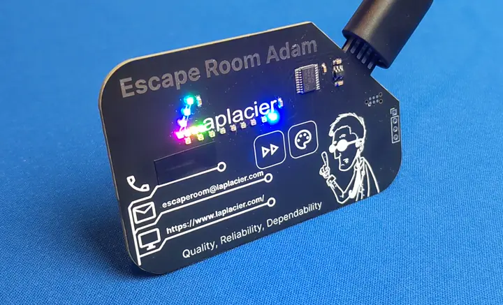
https://github.com/laplacier/PCB-Business-Card-v2
Back in 2018 I was (and still am) an avid reader of Hackaday, a site that collects tech/hobbyist news and writes small blog posts about the material. I opened up the the front page towards the end of the school cycle at my school IT job and stumbled upon an interesting business card design by Mixtela. It was a PCB you could plug in, have it identify itself as a MIDI device and play tunes by creating an analog value when tapping the contacts.
I was so enamored by this design that I wanted to pull out some savings and try to do one myself! This resulted in me taking the first steps in learning how to fabricate custom circuit boards.
My first design had many flaws. Through those flaws, other experiences I gained in other designs, and the fine work performed on the incredibly cost efficient CH32V003 by the open source community, I’ve created a stunner of a business card.
Business Card v1
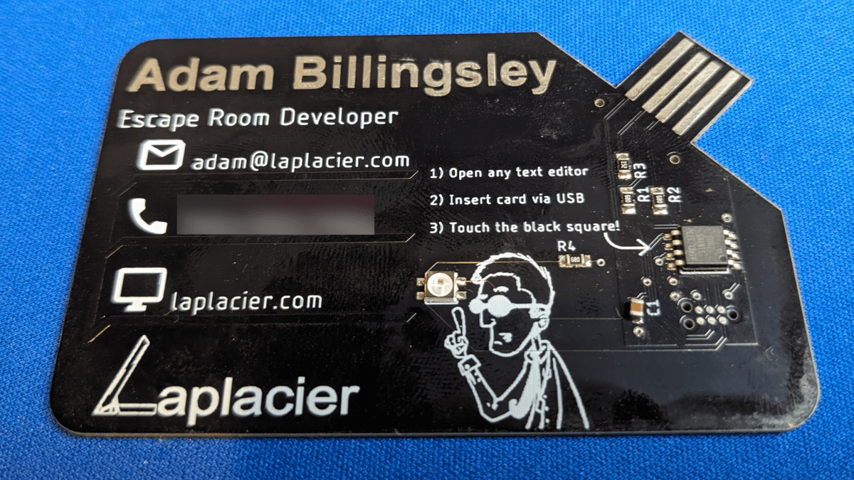
At the time I discovered Mixtela’s business card, I was programming at a basic hobbyist level with Arduino development boards. I also had no experience creating electronic circuits outside of slapping common external components together with dupont cables or solid core wires, following guides with most of the information, and sticking to preexisting Arduino libraries. This is not meant to knock any readers who currently view themselves at this stage. In fact, I hope the first business card design helps you and allows you to take the next step!
Planning
I was completely baffled by the idea that a simple $1.50 microcontroller could become a USB device, and I wanted to make a USB device as well. With my newfound knowledge of a single chip that could accomplish this, I chose the ATTINY85 that Mixtela used on their card. I was helping a local business create escape room electronics as a second gig, so I thought a USB device revolving around revealing a secret would be a novel idea.
I had been buying into the recent hype around the brand new WS2812b addressable LEDs that were taking the hobbyists by storm in this era. While I didn’t know what I wanted them to do yet, they were going on the card.
Mixtela detailed how they were able to use the analog pin on the ATTINY85 to detect which pad was touched. My business card would have a touch pad to activate whatever payload I was going to have on the card.
Prototyping
I had no idea where I could get an ATTINY85 board to test with, so off to the web I went. Turns out, I just missed the window on a Kickstarter for a dev board for the ATTINY85 called the Digispark. However, it was past the point of delivering to backers and it was now selling online. I already had WS2812b LED strips I purchased from Adafruit. With these two items, I had all the parts I needed to prototype ideas.
I slapped both devices on a breadboard and went to town while I experienced down time at work. Thanks to the programming resources provided by Adafruit and instructions for flashing the Digispark on their official site, I had no problems getting basic code running for the LEDs. I plugged in a wire to the analog pin and before I could throw any other components in, I noticed that I could influence the analog value simply by touching the end of the wire. High value means touch, low value means no touch. Great, no components needed (some readers are probably headbanging their desk right now)!
To make the Digispark register as a different USB device, examples were included in the development board config that would facilitate mouse and keyboard input. By running the examples, I could achieve basic text inputs and mouse inputs as described. After brainstorming some use cases, I decided that the business card should type out a secret message when the touchpad is touched and blink LEDs on the card. I used the keyboard example as a template and filled out the remaining LED and touch code.
Designing
I needed to purchase parts for this design. I had only purchased complete boards up to this point, so how do I purchase the tiny little parts that go on a circuit board? I stumbled upon Mouser and Digikey as two sites where I could purchase these parts.
As a first time user, I simply typed in the names of parts I was looking for. However, I became frustrated when the searches yielded either no results or too many results. I looked through many guides and videos of others making PCBs and eventually improved my searches to a point where I could navigate to the parts I needed. In this regard, I had to applaud Digikey for their superior search parameters over Mouser. They’re both fantastic sites and I use them interchangeably today based on price and availability, but for learning the ropes of sourcing SMD components, Digikey became my source.
Time to jump into uncharted territory with PCB design! Today this is no longer the case, but back then EAGLE was free and the software I could find the most resources for. I won’t bore anyone with the full details of what I did, but I want to highlight some key elements that are useful to know when adding aesthetics to a PCB.
Custom Images
If you have a logo or custom image you’d like to insert on your board, it needs to be vectorized. If you’re like me and not an artist or already have an image that isn’t already in vector format (SVG, DXF, etc), there are free tools online that can help make the transition. Be sure that the image or logo you have in mind will look good in monotone black/white and apply the image on the correct silkscreen layer. If you’re looking for basic icons such as an envelope to accent an email address or a phone for a phone number, Font Awesome has some free icons available in the correct format.
Embossing
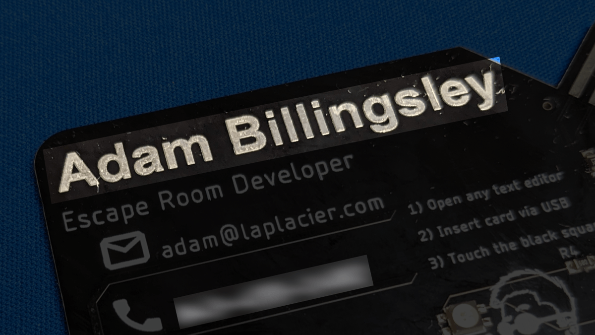
Anywhere copper is not designated on a PCB, it is removed. Copper has a thickness. Even if you have no purpose for the copper as part of the circuit, you can route designs using copper traces and planes that will leave an embossed look under the silkscreen of the PCB.

Masking
When adding a solder mask to the board, silkscreen is not applied to that portion. An experienced reader may be thinking “duh, this is what solder masking does”, but imagine this concept in the context of text or custom images. If you combine a copper plane and a solder mask together, you get a cool metallic look to your design. Neat!
Parts placement
I will preempt this section to say that your first priority is to ensure you are placing your parts in a way that makes sense electrically. Decoupling capacitors should be next to their power pins, differential pairs should be adhered to, and whatnot. While staying within those conditions, be sure to place your components in a way that does not detract from the aesthetic of the board. Oftentimes, you can place them in creative ways that actually improve the aesthetic of the board instead.
USB Connector
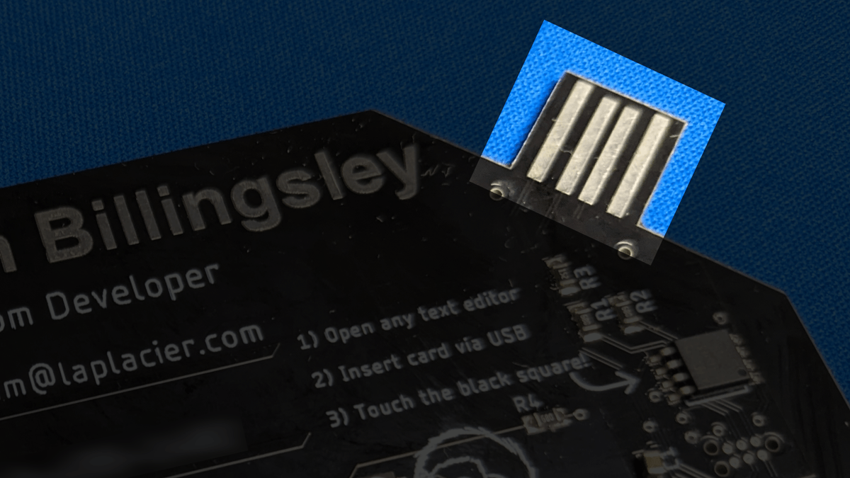
One facet of Mixtela’s design I liked was the cost effective USB connector. It required no additional components, which appealed to me, and the footprint of the connector was applied in the corner in such a way that it maintained pluggability while sacrificing as little of the usable PCB space as possible. I didn’t like how the extra thickness added by Mixtela’s solution looked though. I had access to a 3D printer, so I implemented a similar USB connector but printed out tab thickeners to attach to the back of the PCB. No more bulge was visible from the front, and it still has the required thickness to be inserted.
Parts cost
With the business card being USB powered, I did not need to include any sort of power related components on the board. While it would have been best practice to include protections against reverse polarity and short circuiting, I was not familiar with the inclusion of such concepts as a first time designer. Also let’s be honest; if the business card dies due to improper insertion or injection it’s not the end of the world since the important information is physically listed on the card.
While looking for parts I noticed that WS2812b pixels were quite pricey (they were relatively new, just starting to take off). I instead settled on the SK6812, which operated similarly and had a smaller 3535 size which was more cost effective. It was still pretty expensive at around $0.68 per unit at 100 pieces. Due to sticker shock, I modified my design a bit and limited it to a single LED. I wired this to the ATTINY85 with a series resistor on the data line since I was informed it was best practice to do so (though in 2018 I did not understand the underlying reason why).
The only other component was the ATTINY85 and the passive required to operate it. Resistors were placed on the USB data pins per the USB specification, and a decoupling capacitor was added for the power pin. I purchased a Tag Connect TC2030-NL for the purpose of this build (and many more in the future) and wired the programming interface to this portion. The Tag Connect adapter was a one time $50 purchase, and the passives plus the ATTINY cost about $1.80.
I purchased a roll of black PLA filament for the USB thickener. Excluding the theoretical cost of a 3D printer, and assuming the filament is a one-time purchase due to the minimal quantity needed per card, this was a one-time $25 purchase. There are other costs I will assume in the estimate such as solder paste and other electronics equipment.
I had the boards fabricated from an offshore manufacturer known as Seeedstudio. I don’t remember exactly what the total cost for the PCBs was, but the price wasn’t much different between purchasing 10 or 100 due to shipping, so I planned making 50 and then having 50 spare boards in case I needed more.
Factoring in all of the elements and making estimates for partial usage of certain materials, I was looking at ~$4.00 per business card if I assembled them myself. That was a bit of a hard pill to swallow considering I would be giving these business cards out for free, but the hobby demon inside of me refused to let go, and I went for it.
Labor cost
Back then I considered the learning experience of assembling the PCBs as value in itself. This is certainly not the case today, so let’s evaluate the labor investment.
Strip away the prerequisite knowledge and learning, and let’s focus specifically on planning, sourcing materials and assembly. It took roughly half a day to assemble 50 of these, program them, and test them. It was another day to plan and design the board. How much do you value your labor per hour? Consider the cost of an assembly service versus the cost of making it yourself, factoring in the time invested.
Design flaws
There are major issues with the design of this PCB business card from both a design and concept perspective.
The business card was too expensive to produce to hand it out randomly. This severely impacted the outreach of my business card. I had to really pick and choose who I revealed the business card to because if I showed it to them, they would immediately want it! Call it suffering from success and motivation to do better in this regard.
The card was left reprogrammable through the USB connector. I even told people it was reprogrammable and encouraged them to check out Digispark boards on how to mess around with it. Stop and consider for a moment that if you do this, you have immediately given a bad actor the keys to create a malicious payload on an electronic device with your personal and identifiable information written all over it. If a client plugs in your business card and is harmed by it, they’re likely to assume the bad actor is you. While you may have the best intentions at heart by leaving it reprogrammable, remove those avenues for your sake.
On the same topic, having USB functionality on the business card is, in itself, an issue. We’ve all been conditioned nowadays to never plug in unknown flash drives to our PCs. If you tell a client that your PCB business card “does something cool” when you plug it into the computer, the regular crowd will immediately do so while the more technically inclined will become skeptical and be on guard. If your target audience includes this crowd, you’ll want to decline adding features that discourage the card from being used.
Lastly, the touch capabilities of the PCB business card seldom worked properly. As it turns out, there are lots of design guidelines that need to be adhered to in order to implement capacitive touch directly on a PCB. By relying on touching the ATTINY85 directly, none of those guidelines were adhered to. I’m up to date on these requirements now, but back then I had no idea why it didn’t work sometimes and why I got different results based on which USB powered device I powered it with. I discuss these design rules in the next business card design.
Business Card v2
In spite of the problems presented by my PCB business card, it was an immediate hit no matter who put their hands on it. Having this business card led to increased engagement with clients and paid itself off with those engagements in spite of the cost. Pretty sweet!
After a couple years of carefully handing them out, however, I ran out. I had to choose between assembling some more from the stock I had left or making a new design. I actually chose to finish making all 100. After a while those ran out too, leaving me to either resupply or make a new design. This time I chose to redesign.
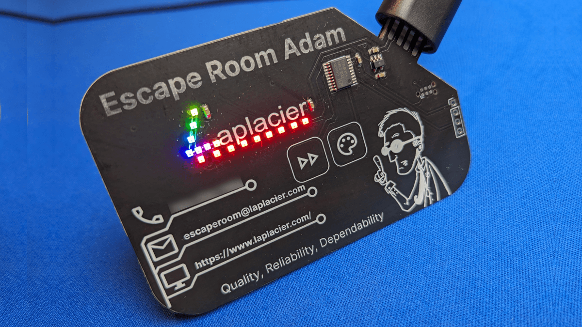
I started and finished the redesign of this business card in January 2024. This time around I have more experience creating custom circuits. Due to self employment, having something to hand to clients that lets me stand out above the rest is more important than ever.
Designing v2
As highlighted from the previous design, the next design needed the following changes:
- Make reprogramming the PCB less accessible
- Reduce parts cost
- No USB features. Make it “dumb” externally.
- Reevaluate the provided features of the PCB.
A new microcontroller called the CH32V003 repeatedly popped up in my feed for a couple of months. Everything I’ve read about it describes it as “the 12 cent microcontroller”. Unless this claim is based on a certain timeframe and quantity I could not see, the cheapest version was $0.18 in units of 100. This was still an incredible price difference compared to the ATTINY85, which has stayed the same even after all these years. I took a look at the available features and a version of the microcontroller that was represented by the development board you could obtain had even more features than the ATTINY85, more GPIO pins, and was faster. While resources for the microcontroller were extremely lacking, an open source community made a reasonably complete toolchain to compile code for the board called ch32v003fun. The price, open source support, and my current use case was enough of an excuse for me to grab the $20 development board and a batch of the $0.21 version of the microcontroller. Much better than $1.50!
One important caveat to this microcontroller over the ATTINY85 is that it is strictly 3.3V, meaning the inclusion of a power circuit to step 5V down to 3.3V is necessary. Since I knew I could get away with using extremely common parts, I limited myself to parts from JLCPCB that were heavily discounted. I’ll talk about that in detail in the cost of parts section.
I needed to decide what my interactive feature for this PCB business card would be. The CH32V003 has pins that are advertised as touch capable, so I decided there would be touch on my board again. While idly browsing available parts at JLCPCB for ideas I came across some extremely small 1x1mm addressable LEDs. I had never encountered addressable LEDs this small before, and they were only $0.04-$0.05 apiece. Prior to this, I was getting increasingly frustrated after searching for hours on end for sensors I could implement with any discernible use case for the casual observer. For the price, such sensors were unreasonable for handing out and these new, adventurous and tiny LEDs were like a breath of fresh air. Due to their low cost and footprint, I decided these would become the exclusive feature for the business card because I desperately wanted to try them out.
Capacitive Touch, but better
This time around I wanted to understand at a fundamental level why the previous touch failed and how to apply that understanding to a successful touchpad in the new design. I found this design guide by Microchip Technology to be one of the easiest to digest guides for people like me who are experienced with electronics, want to implement them in their circuits, but lack the key knowledge of various capacitive touch elements. To help summarize the document, the key things to keep in mind when designing a touch pad as a copper plane to a GPIO pin are:
- The trace from the touch plane to the GPIO pin should be as thin as possible.
- The touch plane should be large enough: bigger is better. For a touch plane under a silkscreen, the recommended size is at least 10mm by 10mm.
- Keep all ground planes and references at least 2mm away from the touch plane and trace connecting the touch plane. More is better.
- Touch planes should be isolated from each other by placing a ground plane between the touch planes.
- If ground plane proximity cannot be avoided, use a hatched pattern for the ground plane in close proximity to the touch plane.
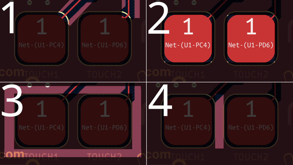
With these in mind, the reason the old design failed is for every single reason listed above except the first one since there was no trace to speak of. I failed to account for all best practices when deciding that touching the ATTINY85 would be the method to trigger the card features. Needless to say, the updated touchpads would be functioning way more reliably compared to my old method.
Powering the microcontroller
I decided to power the board via USB with the same design concept for cost, but remove any USB features. I also needed to power the microcontroller with 3.3V, which required me to step down the voltage from 5V to 3.3V. A common and cheap solution for these voltages is to use an AMS1117 linear regulator. I simply had to include the required passive components, and that was that.
I still decided to skimp out on any protection features for the power. No one was plugging my old business cards into any dubious power supplies, and damaging a business card was still not much of a concern. If you wouldn’t plug your phone into it, don’t use that USB port!
LEDs, LEDs, LEDs
When I found the 1010 addressable LEDs, I knew right away they were going to be an accent to my business logo. I had to decide how many to include on the business card then go from there. I didn’t want to follow the true best practice of a decoupling capacitor between every single LED and decided that decoupling the start and end of the string of LEDs while forcing the power rail for every LED to wall between them was acceptable. With this, I found that I could stuff 16 LEDs on the board before I hit $1.00 in SMD parts cost, so that’s the number I chose.
I first placed LEDs along the first letter of my logo, then evenly spaced out LEDs along the bottom of the logo to underline it. I also took great care to make the trace routing along the LEDs concise and as identical to each other as possible to make it aesthetically pleasing to anyone taking a deep look at the board. It took quite a bit of time to do this while giving the power rail enough thickness to safely provide power to 16 of those LEDs at theoretical max capacity, but the result was worth it.
Programming
Normally I’m pretty quick on the programming side, but with the opponent being the CH32V003 it kicked my butt pretty good. I will warn anyone following along that unless you have a use case for this microcontroller in large quantities (1000+) it is best to avoid using this microcontroller in the projects you’ve been thinking about. There is very little support you can receive with this microcontroller from the manufacturer, aside from the English datasheets that made it possible for the open source community to dive into it. Would I do this again? Yes, because telling people I hand this business card to that it is affordable, and why, has been a valuable talking point.
You can’t get away with writing too much inefficient code with the limited program space, and not only are you limited to coding in C, you will almost definitely be writing a few subroutines in assembly. Smarter folks than I are continuing to work on the open source toolchain for this microcontroller, and if they continue to make great strides in building up the support for it, my opinion on whether to recommend it could change.
At the time I obtained the development board for this microcontroller, example code was contributed to use the SPI bus to run WS2812b LEDs. There were also a few examples detailing different ways to utilize the capacitive features of the microcontroller. This was perfect for me as a starting point.
According to the datasheets, there were multiple GPIO pins capable of capacitive touch, and they could all be activated at the same time by enabling their registers. However, through my testing, I only managed to make two work at a time. Enabling the registers that the datasheet specified as touch capable would make random pins exhibit touch behavior, and sometimes enabling a single register caused multiple pins to be touch capable! I seemed to be the only one experiencing this issue, so without being able to speak Chinese and consult the manufacturer, my only option was to wait 3 weeks for another dev board to see if I maybe had a bad one or settled with two. I didn’t want to wait that long between the design, so I settled with two touchpads. These touchpads became buttons to control the color and animation of the LEDs.
I did not encounter any impossibly challenging difficulties when interfacing with the LEDs. Their timings were almost identical to WS2812b LEDs, and the example code brought the LEDs to life with a little fine tuning. I decided to be a little lazy in this regard and use hard coded NOPs to match the pulse timings well enough to push exactly 16 LEDs worth of information out. Did you know 0 to 1 takes slightly more time to perform than 1 to 0 for the microcontroller? I didn’t until now. Could I have developed a proper method to account for the timings based on any number of LEDs? Probably, but that would have doubled the work required to get the program going and burned, what was at the time, critically expensive time. In this case, the dumb solution is the best solution.

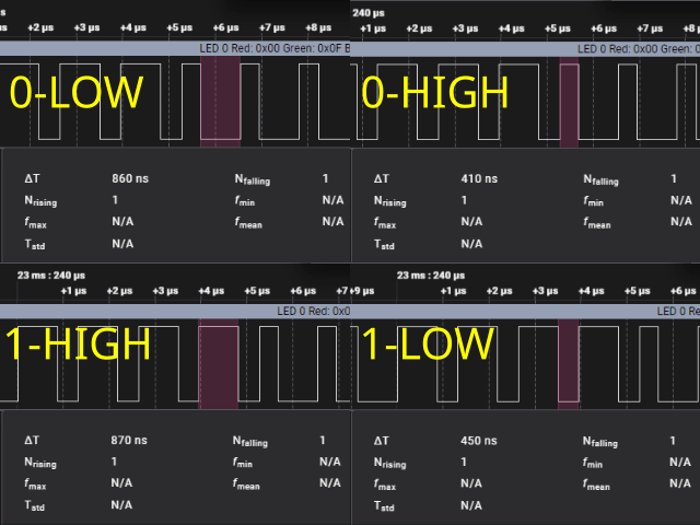
Here’s the correct timings as probed from the CH32V003 going to the LEDs. We can see the the time it took to push the data for a single LED took around 31 microseconds. In our implementation, our 1 bit is HIGH for 870 nanoseconds and LOW for 450 nanoseconds while our 0 bit is HIGH for 410 nanoseconds and LOW for 860 nanoseconds. Per the datasheet of the LEDs, an acceptable HIGH timing for a 0 is between 200-410 nanoseconds, a HIGH timing for a 1 is between 640-1000 nanoseconds, and a frame timing is between 1.1-2.0 microseconds. We barely meet the required timings per the datasheet, and the LEDs function properly as a result. By creating a driver function to perform these timings and sending 24 bits per pixel in this manner, we can drive our LEDs with the CH32V003!
The last thing to implement in the code were animations. To speed up the processing of sine values to assist in brightness values for certain animations, I hard coded two sine tables: one 256 bytes long and one 64 bytes long to use depending on the required speed. I also implemented a color wheel function from WLED (which itself is inspired by Adafruit’s Neopixel implementation) to perform a rainbow effect. Not quite as stunning as if I were to study the HSV graphs in the LED’s datasheet and create form fitting functions based off of that, but no observer is going to be that picky.
I want to highlight a neat little trick I implemented to perform the snake trail animation on the LEDs. Performing loops to create a disappearing snake trail effect on a line of LEDs was causing each loop to require different timings, causing me to despair and assume my only solution was going to be a proper delay timing for LED data pulses, which I was not looking forward to implementing for code I would be unlikely to reuse. Eventually, I figured out that indiscriminately bit shifting the variables storing each pixel’s RGB value to reduce their brightness would reduce their brightness gradually enough to retain the effect and eventually bring them to 0. This solution was very quick for the CH32V003 to process and it salvaged the snake trail animation without requiring any lengthier solutions.
After finalizing all the functions for the LEDs I called them based on the number of touches observed on each touchpad, and viola! The code was ready to go.

The back is free real estate
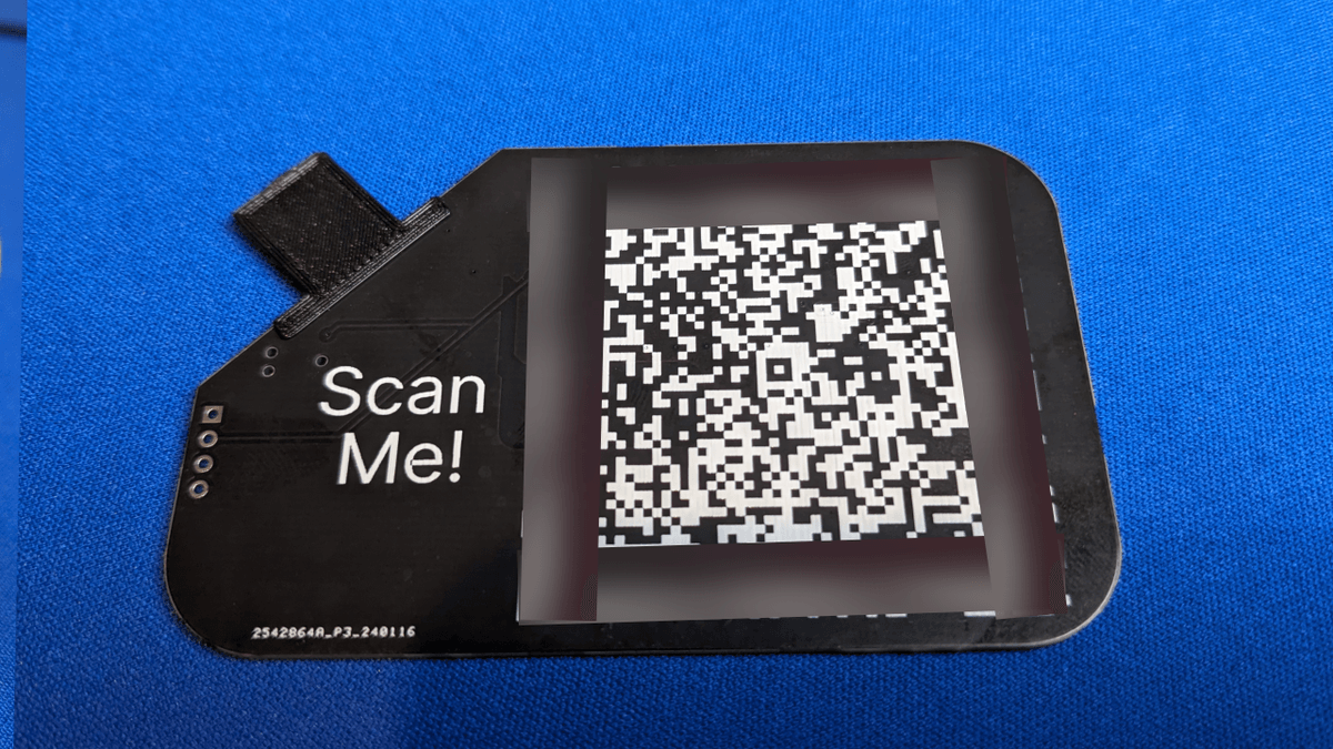
On my original business card I couldn’t think of anything to put on the back, so I just put a small slogan back there. This time I wanted to use that space more effectively and implement a VR Card. Clients can scan the back of my card on their phone and automatically add me to their phone contacts. I struggled to find one that didn’t force you to make an account, charge money, or have its features gutted or missing. At the time of writing, goqr.me is still active and will generate a good QR VR Card for free. I generated one on this site with my contact information and made it as large as possible on the back of my card. The size is probably a bit overkill but I wanted to be sure phones would have no issue scanning it.
Parts cost v2
I priced out and purchased enough parts to create another 100 business cards. The entire SMD parts cost for this board is cheaper than the ATTINY85 by itself at $1.00. Factoring in the cost of the PCBs from JLCPCB at $68.63 and estimating misc materials, we’re looking at a parts cost of around $1.80 per business card. A significant price drop thanks to all the advances we made and experience we gained along the way!
Labor cost v2
Thanks to having 16 very tiny LEDs on each board compared to a single medium sized LED, it takes much longer to assemble these boards. 16 LEDs x 100 is 1600 LEDs to manually pick and place after all.
I designed this board with the option of assembly service in mind. Other than the microcontroller and LEDs, all of the components chosen on this board are considered “Basic Parts” by JLCPCB. For these parts, JLCPCB does not charge a loading fee for the parts and the parts themselves are naturally cheaper per unit since they stock them in absolutely gross quantities. At the time of writing, The entire cost for JLCPCB to create 100 of the PCB business cards and assemble them is $291.69. This brings the cost per board to close to $3. This is, surprisingly, still cheaper than the parts cost of the original business card without assembly. Subtracting the difference from the no labor cost, we’re looking at around $1.20 per card for JLCPCB to assemble each card, or $120 to assemble all of them.
This doesn’t factor in adding the USB thickener, however. That’s going to be personal labor no matter what avenue is chosen.
I decided to assemble these boards myself, working a little overtime each day to knock out the assembly of the PCB business cards a little at a time. I ended up assembling all of them right before attending a business conference, where I passed them out for the first time.
Design flaws v2
This time around, there are no obvious or glaring issues with the business card that I can point to. If I had to really be picky, I would say a new design would not include the phone number on the silkscreen of the PCB. Since there is a VR Card on the back of the PCB, having it on the front in numerical format is redundant and just makes it harder to share safely in photos on the Internet.
Closing Remarks
With the second business card being so cheap, and touch actually working this time around, reactions for this business card went from “that’s really awesome” to “wow, can you make one for me?”
I hadn’t really considered the feasibility of a custom service for these, but with how cost effective the design is I wouldn’t say it’s impossible to do. I’ll have to look at that avenue down the road!
Having these business cards has been an extremely rewarding adventure. It was the hammer that cracked open my insecurities about making custom PCBs, and I’ve definitely obtained contacts that would have otherwise looked the other way over the years without it.
After this batch of 100 is depleted I’ll have to see if any new sensors or LEDs stick out as potential candidates to add to the PCB. That’s going to be quite difficult with how cost effective and impactful the current card already is though! Time will tell.