· Wearables · 11 min read
LED Badge
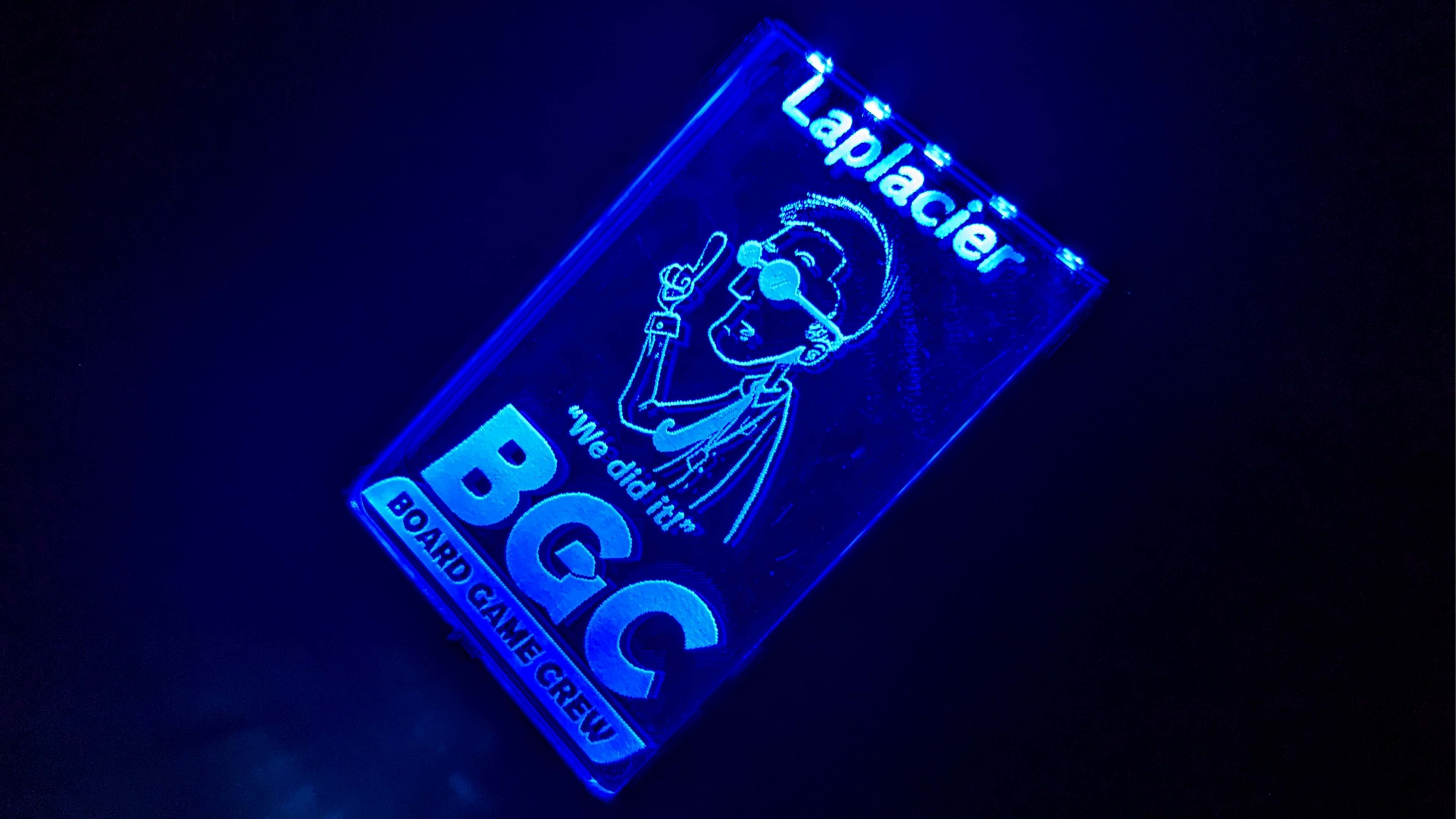
A programmable, reusable, rechargeable edge-lit acrylic LED badge

https://github.com/laplacier/led-badge
Back in 2017 I was a member of a local makerspace called Subproto. I visited the space a lot and frequently used the tools there that I otherwise did not have access to. One day one of the members showed off an edge-lit acrylic name tag they put together with tape, tin foil, and an LED strip. It made a very cool neon sign looking effect and was pretty small, which got my gears spinning. What if I made one into a badge I could wear?
Designing LED Badge v1

For this design, my minimum requirements were:
- LEDs lighting up one edge of the acrylic
- Acrylic thick enough to fully encompass the light emitted from the LEDs
- A CNC or laser cutter to cut and engrave the acrylic
- A battery or portable supply to power the LEDs
- A power switch to toggle power to the LEDs
- Some type of housing to hold the acrylic and electronics secure
For my first prototype I raided the junk drawers of the makerspace for basic parts which met these requirements.
I used a Digispark board as the driver of this project. A Digispark hosts an ATTINY85, which can operate off 5V or 3.3V logic, and a linear
regulator for basic protection. The entire board is also a small form factor which made fitting it into a case much easier. Firmware is flashed on each Digispark that bitbangs a USB
protocol to allow flashing the device over USB. All of these features made it quite simple to implement this board as the driver for the LED badge.
Next was to decide light choices. Static LEDs would be the cheapest option, but not the best option. People can have preferences and being locked into a single color is no fun. I settled on using WS2812b LED strips, which people today may recognize as Neopixels: a name popularized by Adafruit. These programmable LEDs were just starting to take off in popularity in 2017. Each LED is 5V power, can utilize 5V or 3.3V logic, and can have their RGB values and brightness programmed on the fly with a few simple commands. Nothing else on the market came close to having this feature at the WS2812b’s price point, so it was an easy sell.
The badge also needed to be powered in some way. This version of the badge included two coin cell batteries in series to provide 6V off of two 3V batteries. I purchased some battery cases which could be directly soldered into the VIN pin of the Digispark, and included in the case of the design.
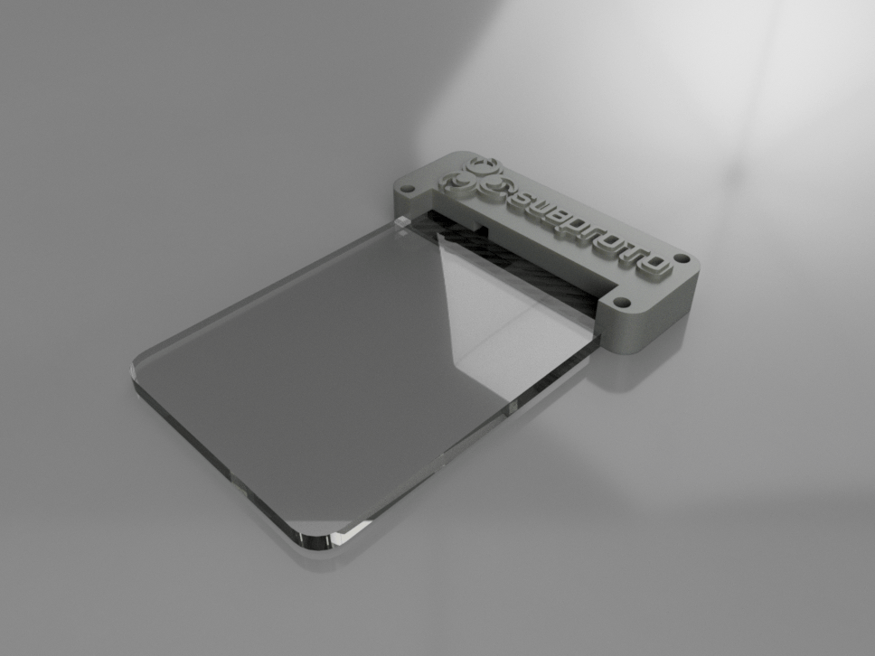
I also used this project as an excuse to learn 3d modeling. I used Fusion 360 to model and plan the design. The LEDs were 5050 sized, which fit snugly along the edge of a piece of 1/4” acrylic, so the badge blank utilized that. Since this design was a remix of a design in the makerspace, I wanted to give credit where it was due and embedded the makerspace logo on the plastic casing. The plastic casing was split into two parts, included tracing to route physical wires from the LEDs and the battery case to the microcontroller, and exposed the USB header of the microcontroller. The acrylic that slotted into the plastic casing included notches to secure it in place. The two halves of the plastic casing screwed together with some small metric screws and the case had slots modeled inbetween the back half to slide in the nuts that the screws passed through.
To produce the case, 3D printing was chosen. I had one available at the makerspace, and it was easy and cheap to create custom cases using a 3d printer. The acrylic blanks for the badge were cut and engraved using the makerspace’s K40 laser cutter.
Analysis of LED Badge v1
This badge did a fantastic job of showcasing the potential of portable, wearable edge-lit acrylic. Each badge was tailored to each wearer’s preferences, and could even include animations such as fading, strobing, and color changing. Compared to the standard color PVC badge, it was above and beyond the top eye catcher at the event it was brought to.
Public reactions of the badges at the event were very positive. No one had seen these types of badges before and were very curious about what they were and how to get one. I built these with flashiness in mind but was still caught unprepared by the amount of interest they garnered.
Parts cost
Converting the price of the LEDs to a per unit price, factoring in the amount of acrylic blanks produceable per sheet at no bulk discount, and purchasing some Digisparks with a small bulk discount, it cost around $7 in parts to produce each one. Not too shabby, considering the product result.
Labor cost
Disregarding the wait time for the 3d printer to produce each case, the process of loading up the machines and custom designs, soldering all the electronics, and assembling the whole unit took me a full 12 hour day to produce 20 badges. Sorting out the programming environment, creating the animations, and building the firmware custom for each user was also a 2-3 day ordeal as I discovered my way through how to communicate with them. There weren’t plug n play libraries all over the Internet for these LEDs like there are today!
Design flaws
There were some issues with the badge at the user level. Indoors, the LED badge showed off its stuff wonderfully. In an overbrightened room, however, the LED effect was barely visible due to the low lumen intensity of 5V LEDs. There was only one room at the event where this was an issue, which had an entire wall dedicated to glass windows that were exposed to outdoor light, so I decided to chalk this problem off as a limitation of LED devices. In the rest of the event’s rooms, you could tell something was going on at the user’s chest level from across the convention: a goal easily met.
The lumen intensity further diminished after only an hour or so of use due to the voltage drop from the included batteries. It was clear that the badge would not be sufficient for prolonged use with the coin cell batteries. Luckily, I exposed the USB header of the Digispark in my design to program them after assembling them, so I was able to direct users at the event to a nearby store to grab an external USB battery to plug into the badge. The smallest version the store carried (2000mAh) was enough to carry the badge through the whole day. Now knowing this, I selected that value as the goal for a design revision.
A common critique of the design was its size and weight. It was *just* enough to be wearable and ignorable, but dangerously bordering the limit of what they felt tolerable for all day use. A small minority of users preferred the larger size due to the extra level of flashiness and obviousness the size provided.
Designing LED Badge v2

The next design needed the following changes:
- Design a dedicated PCB
- Implement a rechargeable battery with ~2000mAh capacity
- Reduce the size and weight
- Improve assembly time
The design needed components to power and operate a microcontroller and LEDs. Version 2 used an ATTINY85 microcontroller: the same as the Digispark from version 1, to simplify the design process. A USB circuit was included to provide power for recharging the battery and a simple program flashing method. With some time passing, a clone of the WS2812b, the SK6812, was introduced to the programmable LED ecosystem and was offerred in a smaller 3535 package, so these were chosen over the WS2812bs. The PCB was two sided with the LEDs exposed on the bottom and other components hidden on top.
A variety of batteries were puchased in small quantities to test their quality and characteristics, and a suitable 2000mAh lithium battery was selected. It hosted an additional feature of having its own battery protection and recharge circuit, which greatly reduced the complexity of the badge PCB.
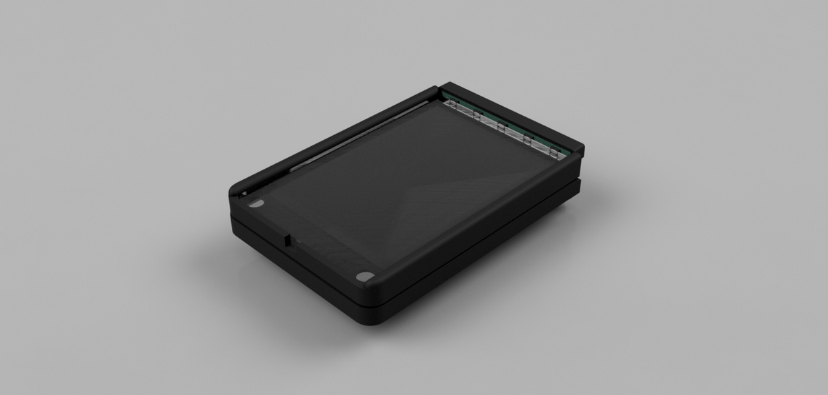
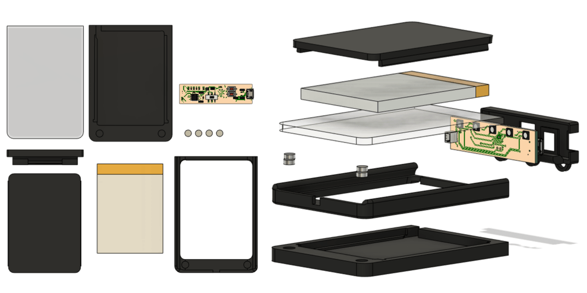
The physical design of the badge needed to be significantly altered due to the size of the new battery. All components could no longer live above the acrylic blank due to the size of the battery. The battery was moved to behind the acrylic blank and covered by the plastic casing. In an effort to reduce size, a standard CR80 credit card shape was chosen for the acrylic blank. With the change of LEDs, an 1/8” thick piece of acrylic was suitable to cover the LEDs rather than a 1/4” piece.
To add a little QoL to the design, the cradle for the acrylic blank was modeled separate from the case to allow the acrylic blank to be easily detachable. This allows a blank to be removed and replaced to be used at different events. To secure this to the case, small magnets are embedded in each corner of the cradle and case to snap the acrylic in place. Two buttons were also implemented to allow the user to change the animation and color of the LEDs on the fly.

Analysis of LED Badge v2
The badge was even more well received on this iteration. Users enjoyed the ability to change the LED color and animation on the fly compared to receiving one pre programmed color and effect. There were no more concerns about the size and weight of the badge, and they perceived the badge as an actual product instead of a cool hobby design. The battery ended up lasting much longer than anticipated, with badges being usable for several days without needing to be recharged.
Parts cost
The PCB plus components ended up being roughly the same pricewise. With the acrylic being smaller and thinner, the unit price per blank decreased as well. However, the addition of a larger lithium battery and 8 small magnets put the parts cost past the original badge.
Labor cost
There were more parts overall for the badge, but due to more careful planning the material assembly was much quicker. All parts had their magnets plastic welded in with ABS solvent, left to dry overnight, then quickly snapped together the next day. The electrical assembly was significantly slower. Organizing all the components, setting up the jigs, hand assembling SMD components on two sides for several PCBs, then checking each one for mistakes after reflowing them was a 2 day process. If producing these beyond a small quantity, paying for the fab house to assemble these boards would be a worthwhile investment.
Design flaws
The acrylic blank swapping feature was met with slight interest, but otherwise glossed over. No one has the ability to walk over and pull a new acrylic blank off the acrylic tree. They had no way to source a new design to swap out their original later on. Selling additional blanks and continuing that service would lead to a steady source of cashflow, but without that service the feature is rendered ineffective. Design time was lost implementing this feature.
The badge’s center of gravity and hinge point caused the badge to sometimes flip around, requiring the wearer to flip it back to the front. Since the battery ended up being overkill, a smaller battery placed closer to the hinge could alleviate this issue.
Future improvements and remarks
The second iteration of the LED badge has performed sufficiently for its intended use case. The following would need to be improvised to continue producing the product:
- Change the microcontroller. ATTINY85s haven’t gotten any cheaper or advanced in any meaningful way, and microcontrollers as low as 22 cents exist on the market that can control addressable LEDs.
- Smaller addressable LEDs are now available as small as 1mm (1010). Thinner acrylic can be utilized, further decreasing the size of the design. In spite of requiring more LEDs to fill the same space, the price point per LED makes them cheaper to implement as well.
- Keep the idea of an interchangeable acrylic blank, but implement its replacement naturally as a function of assembly. Simply reversing the process of assembly should allow the acrylic to be removed. Don’t overengineer the design in a way that makes its addition unnecessary.
- Reduce battery size. Ideally a battery would be implemented to allow the case to return to being a top attachment to the acrylic blank, if one could contain enough capacity to operate a badge for a meaningful amount of time.
- Protect the power switch properly. Over the years, the power switches have rusted and are producing poor contact as a result. A little plastic housing and grease would go a long way to extend the longevity of the switch.